15
Siemens Schweiz AG A6V11646018_en--_k
Smart Infrastructure 2023-02-27
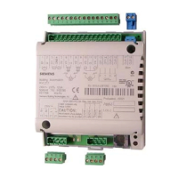
Connection terminals
Terminal Symbol Description Module Channel
1, 2 2 x RJ45 interface for Ethernet with switch
3, 4 KNX PXC4.E16: KNX PL-Link
5, 6 24 V ~,
⏊
Operating voltage AC24V
7 Functional ground (must be connected on the installation side with
the building grounding system (PE)).
9 to 17
20 to 28
Ux Universal inputs / outputs 1…12 61 1…12
⏊ Measuring ground for Ux
8, 19 V+ DC 24V power for field devices 2.4W / <100mA
18, 29 V~ AC 24V power for field devices 48VA / 2A
68, 69, 70 COM PXC4.E16: Interface EIA-485 (Modbus RTU)
Term on, off PXC4.E16: Switch for bus termination
Polar on, off Switch for polarization
75 to 86 DOx Relay outputs 1…4 11 1…4
Wiring lines for field devices
Wiring length max. 300 m (1,000ft), CU wire or CU strand.
Cross-section depending on the signal
30m (100ft) applies for signal types AI NTC10K and AI NTC100K
or 300m (984ft) with shielding
Examples of connection diagrams for universal inputs/outputs
Digital inputs
S1 Feedback contact (NO)
S2 Feedback contact (NC)
Count inputs: Counter inputs, that count faster than 1 Hz and are laid with more than 10 meters using analog inputs in
the same cable duct, must be shielded.

 Loading...