Siemens Industry, Inc. A6V10356958_en--_n
Smart Infrastructure
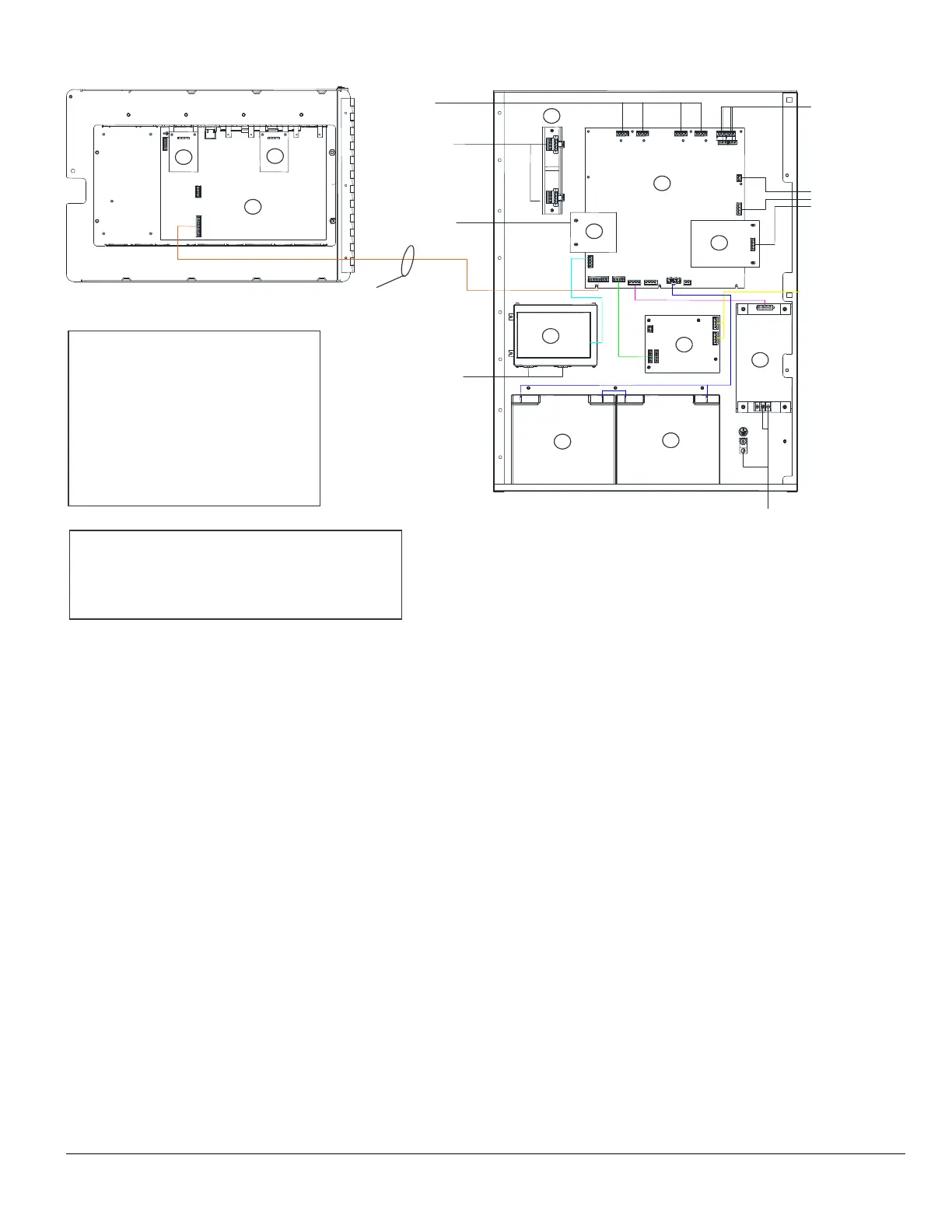
Figure 1: Module Location in 2HU Enclosure and Recommended Wire Routing
Knockout
#7
Knockout
#8
Knockout
#9
Knockout
#3
Knockout
#4
Knockout
#5 or #6
Knockout
#10 or #11
Ribbon Cables
Recommend Wiring Routes:
Knockouts: 1, 2, 3, 5, 6 are Non-Power Limited wiring only
Knockouts: 4, 7, 8, 9, 10, 11 are for Power Limited only
Notes:
Refer to Table 5 to locate each module wiring diagram.
Module Locations:
1. FCM2018/FCM2019-U3 Operating Unit
2. FN2001-U1 SafeDLink Module
3. FCA2016-A1 RS485 Module
4. FCI2016/FCI2017-U1 Periphery Board
5. FCI2020-U1 City Tie/Municipal Ckt
6. XCI2001-U1/FCI2011-U1 Releasing/NAC
7. FN2006/FN2007-U1 Network Module
8. FCA2015-U1 DACT
9. FP2011-U1/FP2012-
10. Battery Set
11. FHA2031-
Knockout
#1 or #2
1
2
3
4
5
6
7
8
9
10
10
11
 Loading...


