Siemens Industry, Inc. A6V10356958_en--_n
Smart Infrastructure
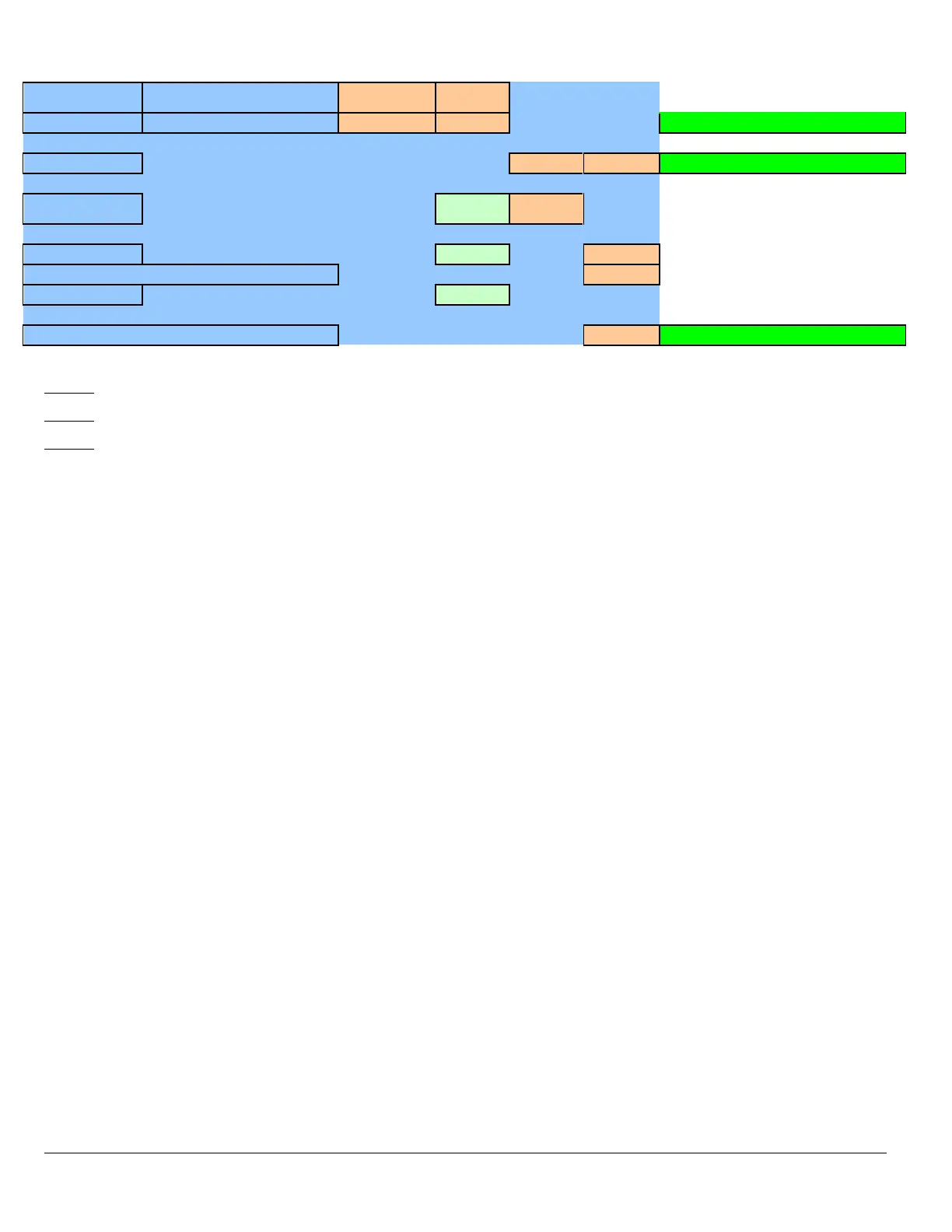
PAD-5-CLSA
Class A/B Expansion Board w/
Releasing 0.00000 1.25 mA per board
Total 0 0.000 (included above) System OK
Total Current 0.000 0.000 Use 170W power supply
(hrs) 24 0.00
Alarm Time (min) 30* 0.00
AH required (no reserve) 0.00
Battery Reserve 125%
AH Required (with reserve) 0.00 System OK
Note 1: Ensure that the standby Aux power is not entered twice when used as external power source for optional modules.
Note 2: Max Alarm NAC Current = 3A/Circuit, Max Releasing Circuit Current = 2A/Circuit
Note 3: *Alarm time requirements offer multiple selections. Choose the appropriate time based on the requirements of
your application. Options include: 5 minutes, 10 minutes, 15 minutes, 30 minutes, 60 minutes, and 120 minutes.
Battery Calculation
Battery backup is required for compliance to UL864 and ULC-S527. Refer to NFPA 72 and CAN/ULC-S524 for required
standby time. To determine the battery, use Table 7 above and fill-out the required parameters.
1. Record quantities of all required modules and devices per panel.
2. Device Load Calculation: Place the # of devices in the yellow column, multiply with the current draw and place results
in
Standby/Alarm
column. Add all results in the
Standby/Alarm
column to determine the total device current draw and
place the result in the appropriate
SLC load
cell.
3. Module Load Calculation: Place the # of modules and associated functions (e.g., LED zones, Bell Follower, etc) in the
yellow column and multiply with associated current draw and place results in the appropriate column (Standby or
Alarm).
4. Place the NAC load and Releasing load during alarm in the
Alarm
Column.
5. Add all results in the Standby Column to determine the
System Standby
Current.
6. Add all results in the Alarm Column to determine the
System Alarm
Current.
7. Place the required parameters: Standby Time (hr), Required Alarm Time (hr), Minimum Battery Size (AHr), Minimum
Battery Reserve (%)
8. Calculate Battery Requirement for System Standby (AHr) = System Standby Current (A) x Standby Time (hr)
9. Calculate Battery Requirement for System Alarm (Ahr) = System Alarm Current (A) x Alarm Time (hr)
10. Calculate the Battery Reserve (AH) = (Battery Reserve (%) / 100%) x (System Alarm Req + System Standby Req)
11. Calculate the minimum battery Requirement = Battery Reserve + System Alarm Req + System Standby Req.
Select the battery that meets or exceeds the final calculated amp hour rating.
 Loading...


