Siemens Industry, Inc.
Building Technologies Division
8, Fernwood Road
Florham Park, New Jersey 07932
www.siemens.com/buildingtechnologies
Siemens Canada Limited
Building Technologies Division
2 Kenview Boulevard
Brampton, Ontario L6T 5E4 Canada
© Siemens Industry, Inc. 2012-2016
Data and design subject to change without notice.
A6V10324662_g_en_US
2016-01-20
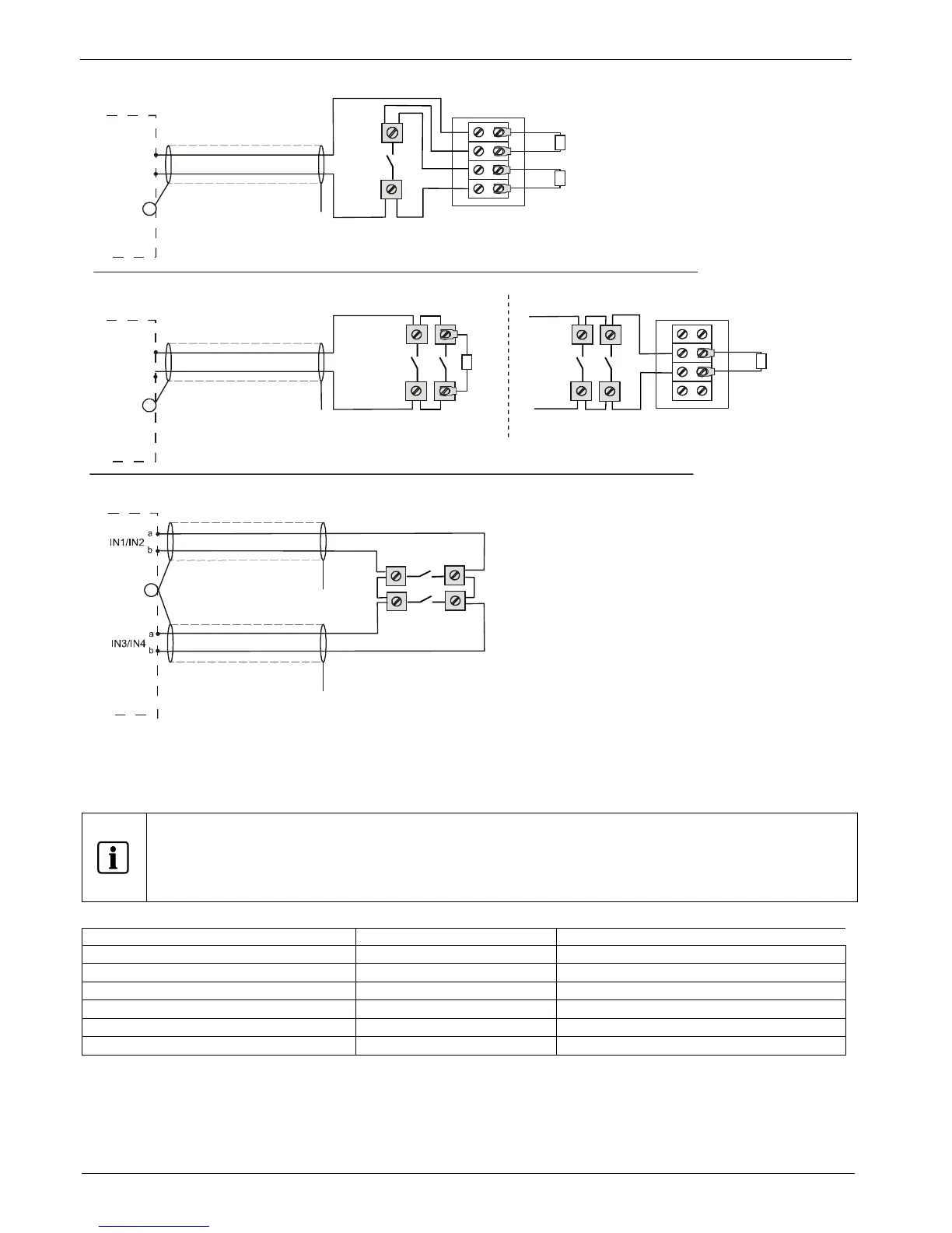
End of Line Resistor Wiring Overview
① CAUTION: FOR SYSTEM SUPERVISION – FOR TERMINALS IDENTIFIED WITH A ① DO NOT USE
LOOPED WIRE TERMINALS. BREAK WIRE RUN TO PROVIDE SUPERVISION OF CONNECTIONS.
② Use Siemens TB-EOL terminal P/N S54322-F4-A2 or equivalent.
③ Use only normally open dry contact SWITCHES for the inputs
Figure 11 Wiring end of line and switch
Use a 4 or 2 pole UL/ULC recognized SWITCH.
·
Switch Terminal must be capable of two conductors at one terminal.
·
EOL Resistor wiring must be done according to UL 864 and ULC-S527, chapter ‘EOL Devices’.
· The EOL Resistors must be connected at the end of the input lines.
·
No addressable device or 2
wire smoke detectors can be connected to the inputs.
inch adapter plate (optional)
SHIELDED WIRE MAX: 200 FT
18 - 14 AWG
OPEN AND SHORT SUPERVISION
OPEN
CLASS B STYLE C, OPEN AND SHORT WIRING SUPERVISION
SHIELDED WIRE MAX: 200 FT
18 - 14 AWG
X
EARTH
GND
CLASS A STYLE D, OPEN WIRING SUPERVISION CAUTION: BE AWARE OF THE INPUT POLARITY IN CLASS A MODE
SHIELDED WIRE MAX: 200 FT
18 - 14 AWG
OPEN
OPEN
X
GND
CLASS B STYLE B, OPEN WIRING SUPERVISION
OPEN SUPERVISION
X
EARTH
GND
for UL: mount EOL directly on the last SWITCH terminal for ULC: mount EOL on the TB-EOL terminal
TB-EOL ②
TB-EOL ②
SWITCH ③
SWITCH ③
SWITCH ③