4BMounting / Installation
| 138
2015-11-04
5.5 Cable entry
The detector bases contain a spring clip. Permissible wire/strand cross-section
0.28…1.5 mm².
Note the positive and negative poles.
Only connect one wire per terminal. This is the only way to ensure the connection
is failure-free for the entire service life of the device.
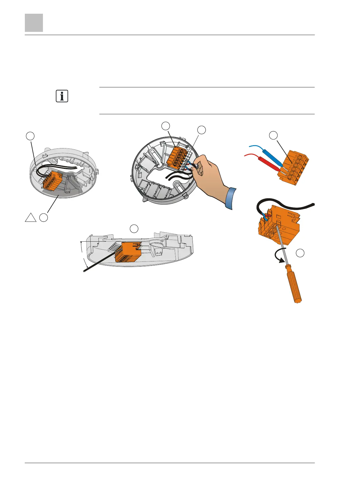
Cable entry in detector base
1 The conductor loops must be placed flat in the base bottom. 5 Contact for test tips
2 The conductor loops must not be placed over this zone, as
otherwise the detector cannot be inserted correctly.
6 Turn the screwdriver 90° in the direction of the arrow to remove
the conductor or insert a strand.
3 Screwless connection terminals 7 Optimum insertion of the wire without tool, at an angle of
approx. 30°
4 Bare length 6.5…7.5 mm
 Loading...