EasyManua.ls Logo

Siemens FireSeeker FS-100

Siemens FireSeeker FS-100
50 pages
To Next Page IconTo Next Page
Loading...
Siemens Building Technologies, Inc. Siemens Building Technologies, Ltd.
8 Fernwood Road 2 Kenview Boulevard
Florham Park, NJ 07932 Brampton, Ontario L6T 5E4 CN
P/N 315 -699461-1
(447290)
Fire Safety
FireSeeker
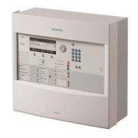
Fire Alarm Control Panel
Model FS-100
Installation, Operation, and Maintenance Manual
Technical Manuals Online! - http://www.tech-man.com

Table of Contents

Question and Answer IconNeed help?

Do you have a question about the Siemens FireSeeker FS-100 and is the answer not in the manual?

Siemens FireSeeker FS-100 Specifications

General IconGeneral
BrandSiemens
ModelFireSeeker FS-100
CategoryFire Alarms
LanguageEnglish

Summary

MINIMUM CONTROL UNIT CONFIGURATION

Power Supply

Details on the 24V nominal power supply and battery charging.

Addressable Device Circuit

Configuration of the single addressable device circuit.

Notification Appliance Circuits

Details on the four independent NACs.

RS485 Communications Circuit

Specifications for the RS485 communication circuit.

Status Relays

Information on the provided alarm, trouble, and supervisory relays.

AUXILIARY MODULES

ADDRESSABLE DEVICES

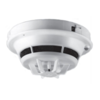
Siemens Addressable Detectors

Overview of addressable detectors and their operation.

PROCESSOR CONTROLLED OUTPUT ZONES

EVENT HISTORY

GENERAL SPECIFICATIONS

RS485 COMMUNICATIONS CIRCUIT

Remote Device Power

Powering remote devices on the RS485 circuit.

Remote Device Data

Wiring methods for RS485 data transmission.

Addressable Device Circuit

CONTROL UNIT OPERATION

OPERATION INSTRUCTIONS

Detailed step-by-step procedures for operating the control unit.

Standby Condition

How the system operates in normal standby mode.

Alarm Condition

System response and procedures during an alarm event.

Positive Alarm Sequence (PAS)

Details on the delayed alarm sequence feature.

Pre-Signal

Operation of the pre-signal alarm mode.

Trouble Condition

Supervisory Condition

Maintenance

FS-100 OPERATING INSTRUCTIONS

Alarm Operation

Procedures for handling alarms on the FS-100.

Trouble Operation

Procedures for handling troubles on the FS-100.

Normal Standby Condition

Indicators during normal system standby.

FS-RD OPERATING INSTRUCTIONS

Alarm Operation

Handling alarms for the FS-RD annunciator.

Trouble Operation

Handling troubles for the FS-RD annunciator.

CONTROL UNIT INSTALLATION

Surface Mounting Instructions

Semi-Flush Mounting Instructions

AC Supply Connection

Battery Installation

Powering the Control Unit

System Wiring

Check System Operation

SYSTEM WIRING

CONTROL UNIT WIRING OVERVIEW

Diagram showing the arrangement of boards and connections.

WIRING SEPARATION

PRIMARY AND SECONDARY POWER WIRING

STATUS RELAYS AND AUXILIARY POWER OUTPUTS WIRING

System Power Requirement Calculations

Guide to calculating total system power needs.

Battery Size Calculations

Method for determining appropriate battery capacity.

NAC WIRING

ADDRESSABLE DEVICE CIRCUIT

Addressable Device Wiring Diagrams

Diagrams illustrating connection styles for addressable devices.

Addressable Devices

Addressable Detectors

FS-DPT Photoelectric Detector with Thermal

Specifications for the FS-DPT detector.

FS-DT Thermal Detector

Specifications for the FS-DT thermal detector.

Addressable Modules

PROGRAMMING THE CONTROL UNIT

PROGRAMMING SECURITY

Levels of security and password protection.

MAINTENANCE

QUICK TEST (WALK TEST)

BATTERY SIZE CALCULATIONS

APPENDIX C: TROUBLESHOOTING

B. System Troubles

C. System Events

Related product manuals