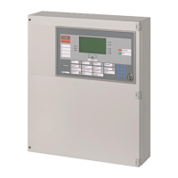
FS-100 Installation & Operation Manual
P/N 315-699461 24
L. Checking Supervised Circuits
To check the supervised circuits of the control unit:
1. Place a 24K ohm resistor (color-coded: red, yellow, orange) across each set of NAC terminals.
2. Push SYSTEM RESET button.
3. The SYSTEM TROUBLE LED, and the trouble buzzer should be off.
4. Discard 24K ohm resistors after initial testing is complete
M. Optional Modules
Follow the installation instructions provided in Appendix D.
N. System Wiring
Before connecting the field wiring, check the wiring for opens, shorts, grounds and stray voltages.
Warning: Damage may result if a high voltage insulation tester is
used on wiring while connected to the control unit.
Terminate the field wiring to the main board in accordance with the diagrams in Section V and the system
design documents.
NOTE: All wiring must be in accordance with local codes and the National Electrical Code. Use
only FPL, FPLR and/or FPLP as described in Article 760 of the National Electric Code.
O. Check System Operation
Check for proper operation of all the system functions. See Section II for Operation Instructions.
Technical Manuals Online! - http://www.tech-man.com

 Loading...