FS-100 Installation & Operation Manual
P/N 315-699461 30
ADDRESSABLE DEVICE CIRCUIT
The basic configuration of the FS-100 control unit includes one addressable device circuit. The devices
are polled by the control unit every few seconds and input or output functions communicated to determine
device status or function. The control unit monitors all device addresses for alarm and trouble conditions.
Addressable Device Wiring Diagrams
Proper connections for UL Listed compatible addressable devices are indicated below. Refer also to the
instruction sheets packed with each device.
Detectors and modules may be wired together according to several NFPA defined wiring styles. The
wiring style that is appropriate for your installation should be determined from the relevant building codes
and the Authority Having Jurisdiction.
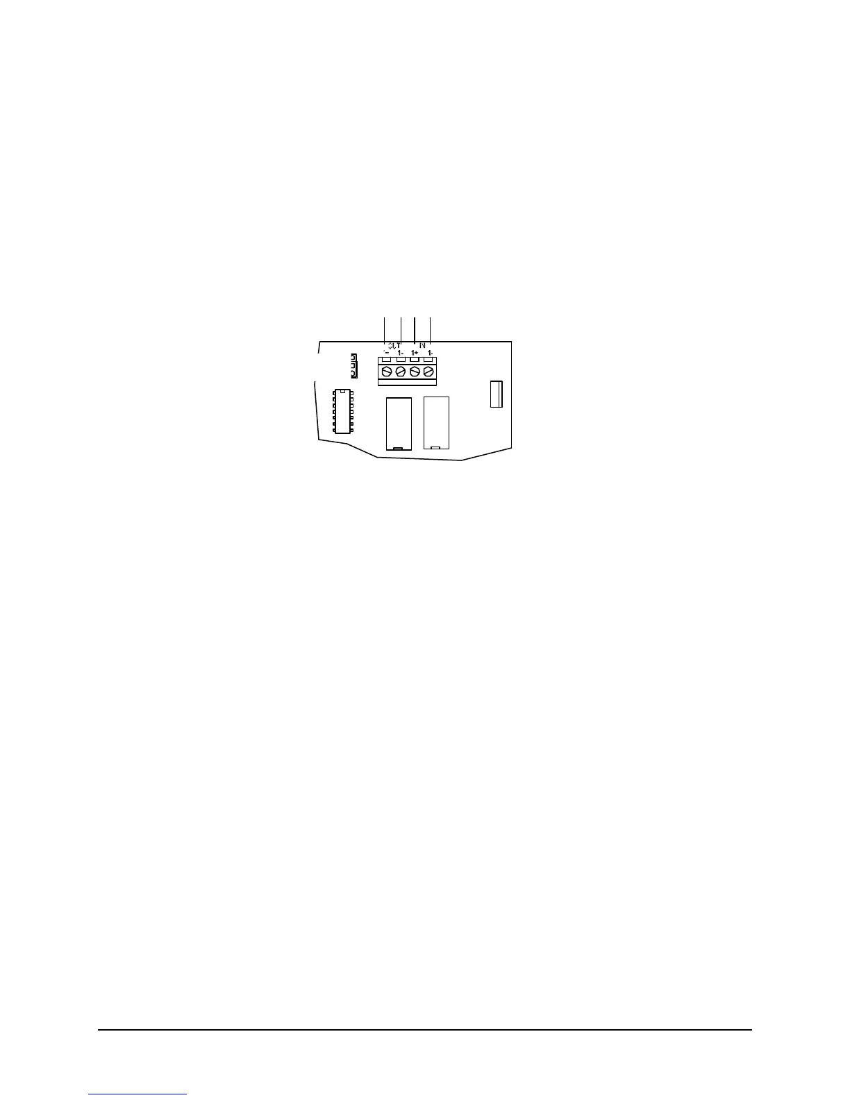
Addressable Device Circuit
Style 4 or 6/7 Operation
(set jumper P1 for proper style)
24VDC nominal
Wire Resistance-20 ohms/line
Supervised, Power Limited
See Installation & Operation Manual Appendix B
for Compatible Devices
Style
6/7
4
Technical Manuals Online! - http://www.tech-man.com

 Loading...