FS-100 Installation & Operation Manual
P/N 315-699461 27
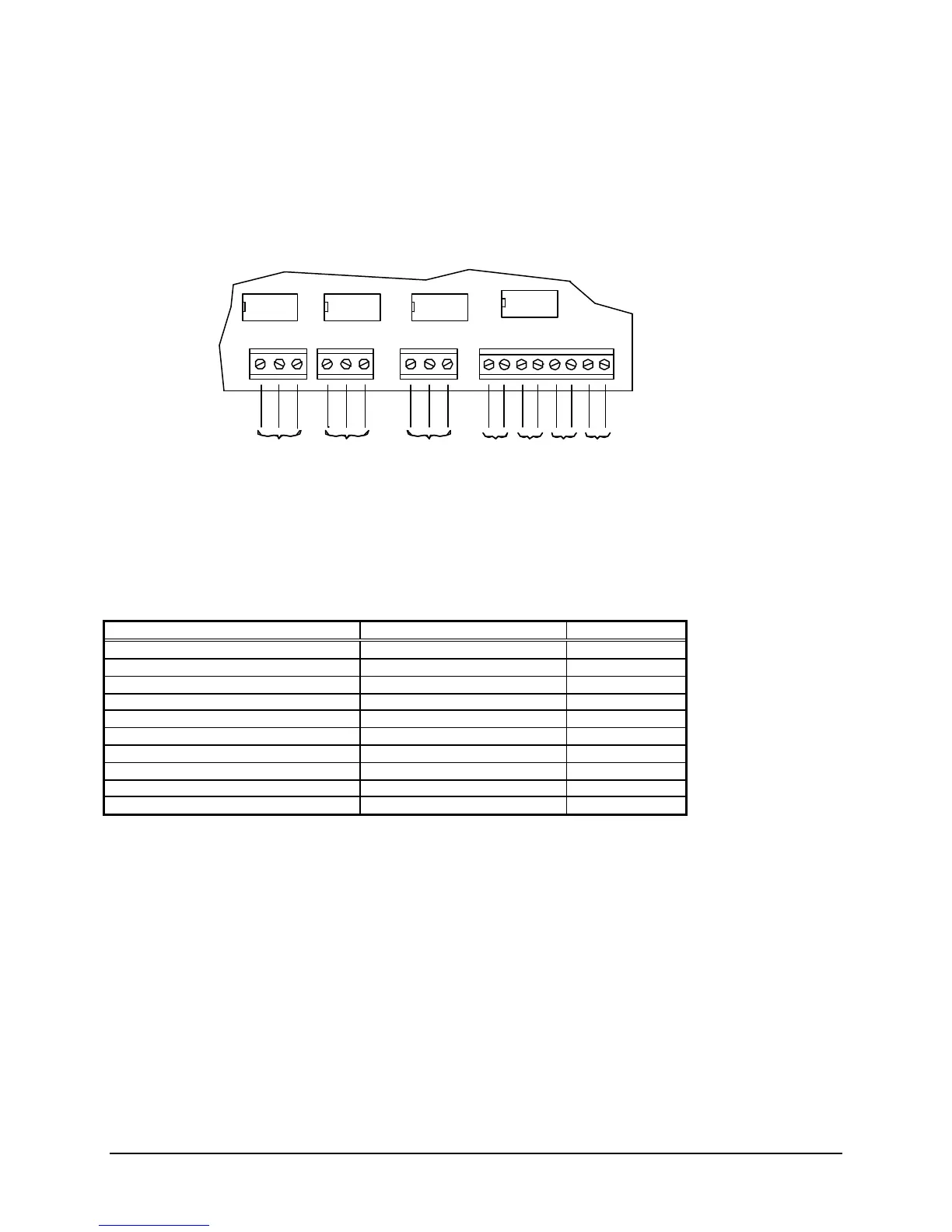
STATUS RELAYS AND AUXILIARY POWER OUTPUTS
WIRING
The right lower edge of the main board provides for connection of contacts and auxiliary power
connections.
System Power Requirement Calculations
Device Item Max.(Amps) Total (Amps)
FS-100 Control Unit 0.200 0.200
Addressable Device Circuit Power # of Devices X 0.0002 Amps
Auxiliary Power Outputs * Depends on devices installed
FS-MT Municipal Tie Board 0.055
FS-232 RS232 Communication Board 0.008
FS-DACT Dialer Communicator Board 0.054
FS-RD Remote LCD Annunciator * 0.030
FS-RU/RE8 Serial Relay Unit * 0.030
FS-SAU/SAE16 Serial Annun. Unit * 0.030
Total must not exceed 0.75 Amps
Auxiliary Power Supply
* Connect a UL Listed auxiliary supply when the power requirement calculation indicates that an
additional source is required.
Battery Size Calculations
For calculation of battery size requirements see appendix A.
ALARM TROUBLE SUPERVISORY
- + - R - + -
(Shown in normal standby condition)
1A@28VDC max., Resistive
For Power Limited Source, Unsupervised
0.4A max.@24VDC nominal
Unsupervised, Power Limited
(Maximum current of all auxiliary outputs,
RS485 Circuit and option boards is 0.5A.)
A – Common
O – Normally Open
C – Normally Closed
Technical Manuals Online! - http://www.tech-man.com

 Loading...