FS-100 Installation & Operation Manual
P/N 315-699461 23
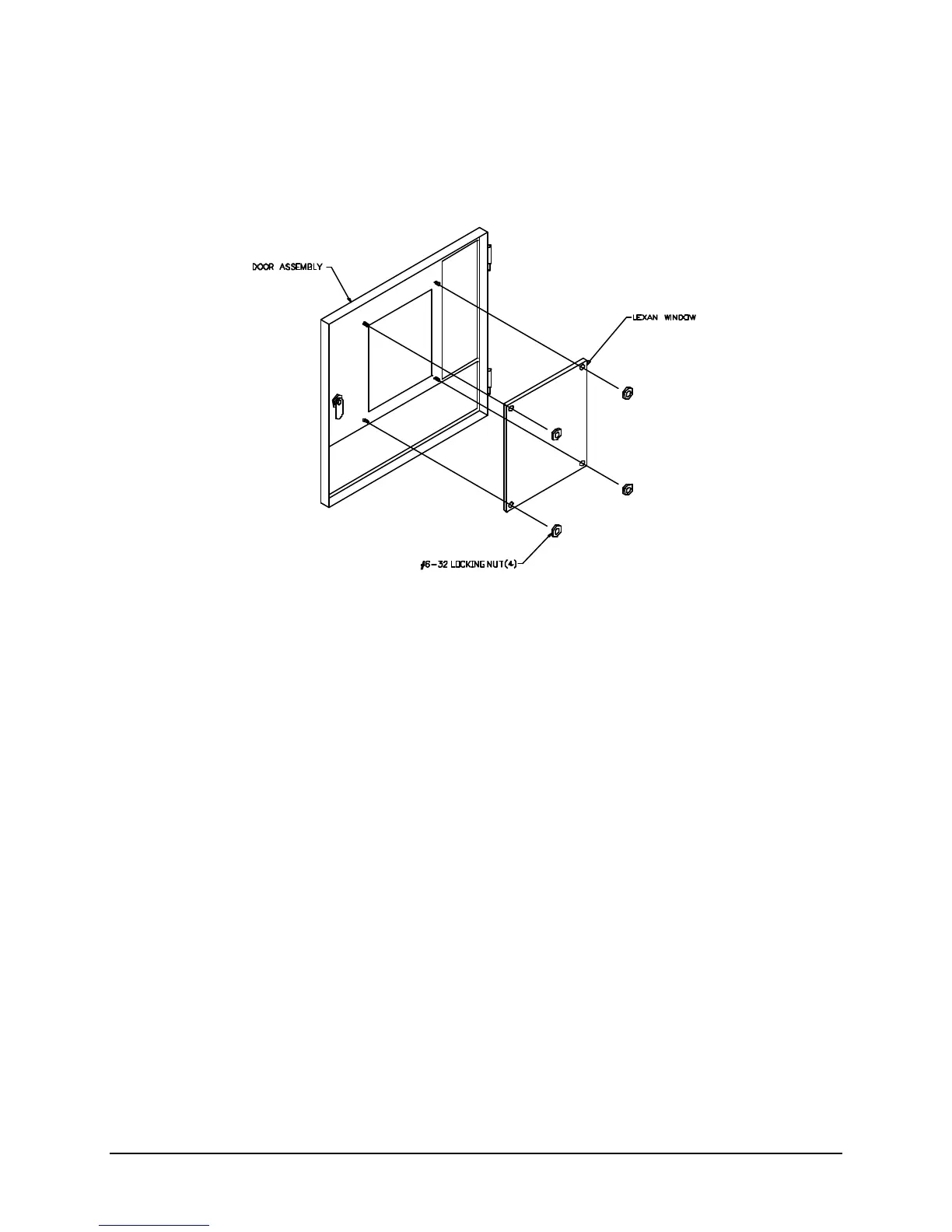
I. Door Assembly
1. Secure the Lexan window to door assembly using four #6-32 locking nuts.
2. Place the Door Assembly onto hinges of the Back-box Assembly.
J. Battery Installation
Warning: Improper battery connections or shorting battery terminals may
damage the system and/or batteries and may cause personal
injuries.
Place the batteries in the space provided in the bottom of the back-box. If larger than 7 AH battery set is
required, a separate enclosure must be used. The Siemens Model BB-55 may be used for battery sets
55 AH and smaller. The FS-100 battery charging circuitry can only support systems requiring up to 38 AH
battery sets.
The control unit uses a 24V battery set. Connect the two 12V batteries (or four 6V batteries) in series
with #12 AWG wire, minimum. Route the battery leads to the left of the enclosure and up to the battery
termination block, TB5. The battery leads are not power-limited.
Observe polarity. Connect the B- terminal from the main board into the black or - terminal of the battery
set and the B+ terminal from the main board into the red or + terminal of the battery set.
K. Powering the Control Unit
Apply AC power to the control unit. AC POWER ON LED, SYSTEM TROUBLE LED, and the trouble
buzzer should be on.
Technical Manuals Online! - http://www.tech-man.com

 Loading...