4BMounting / Installation
47BDetector heating unit FDBH291
| 138
2015-11-04
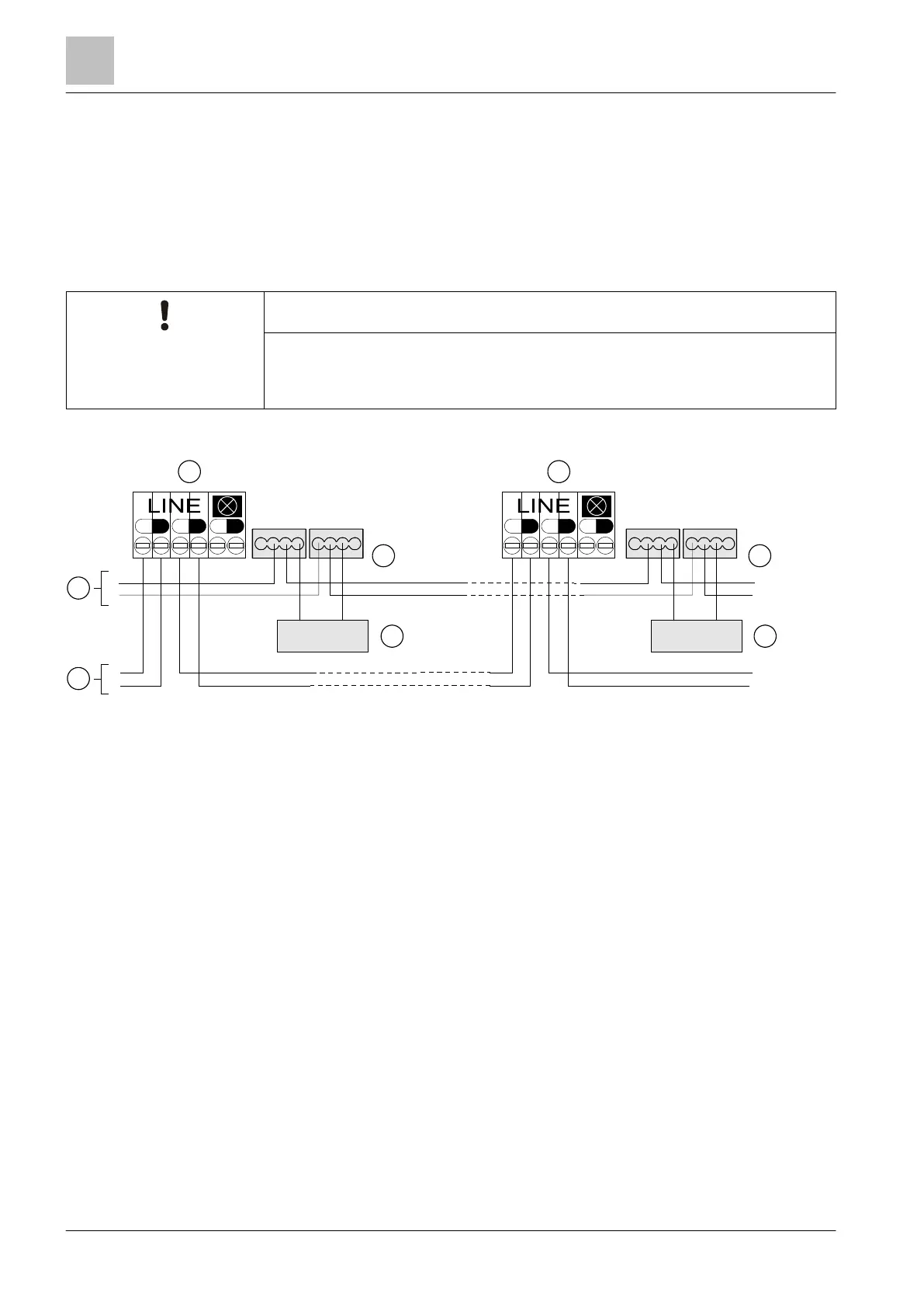
5.17.2 Connection of the detector heating unit
● Connect the cables for the monitored supply from the control panel and the
detector heating unit to the supplied micro terminals DBZ1190-AA.
● The cables can be placed in the same cable harness as the detector line or
separately.
● Several detector heating units can be connected in parallel.
● Detector heating units require a separate supply.
Malfunction
To ensure smooth operation, the detector must be checked regularly for icing.
Connection diagram for detector heating unit FDBH291
1 Detector base 4 Control panel
2 Micro terminals 5 Control panel supply (monitored)
3 Detector heating unit
+
-
+
-
+
-
+
-
DBZ1190-AA
-
+
LINE
FDBH291
+
-
+
-
+
-
-
+
FDBH291
-
+
DBZ1190-AA
FDB221/FDB221-AA
FDB222
FDB221/FDB221-AA
FDB222
1
2
1
2
33
4
5
 Loading...