Mounting / Installation
22
Building Technologies 007025_i_en_--
Fire Safety & Security Products 07.05.2010
5.2 Electric connection
Note the positive and negative connections.
Only connect one wire per terminal. This is the only way of ensuring a problem-
free connection over the device's entire service life.
You will need at least one auxiliary terminal to connect the base sounder. Two
micro terminals DBZ1190-AA are included in the scope of supply for the
sounder base.
The external alarm indicator must always be connected using auxiliary
terminals.
Use unshielded cables if possible.
Select auxiliary terminals of the appropriate wire diameter.
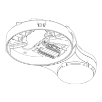
Position the auxiliary terminals in the sounder base (see figure).
If using shielded cables:
‒ Connect the shielding of the detector line cables using an auxiliary terminal.
‒ Connect the shielding of the external alarm indicator cable with the positive
pole of the external alarm indicator connection.
‒ The shielding must not touch any external potentials.
For more information about using shielded cables, see document 007004.