Siemens Industry, Inc.
Building Technologies Division
P/N 315-034850-83
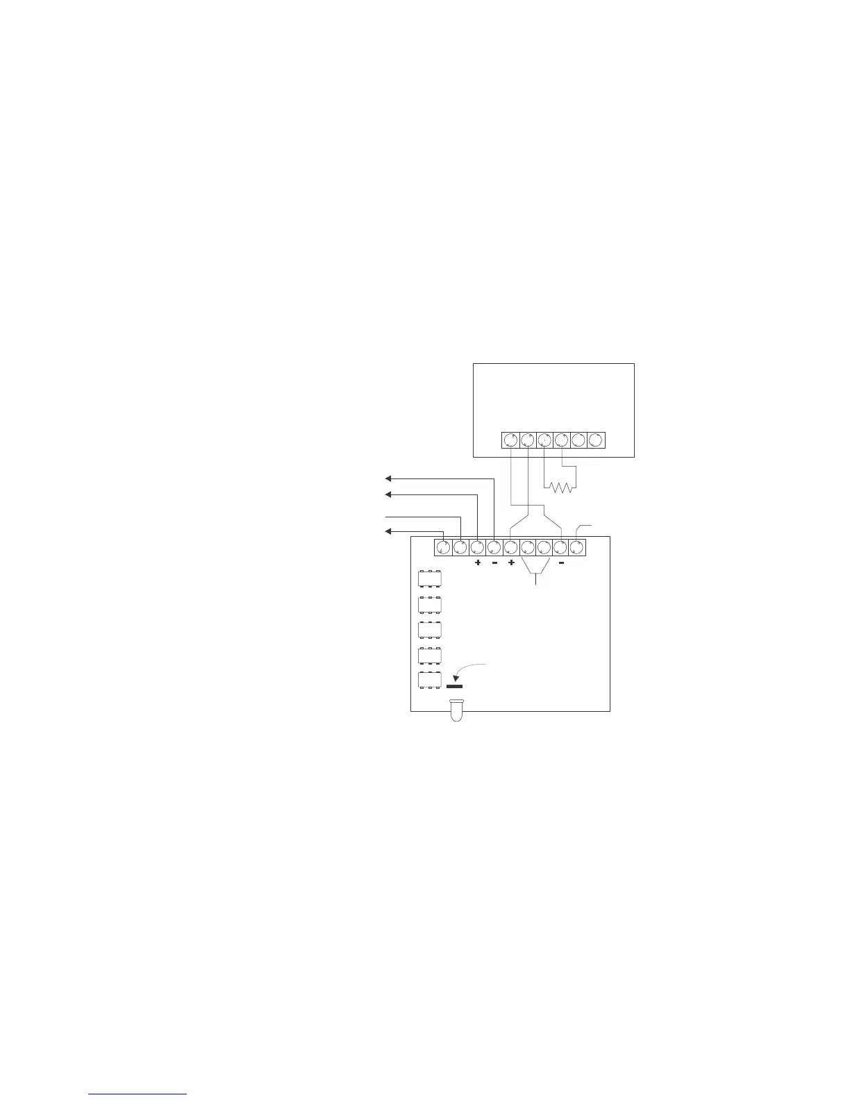
Figure 4 shows the wiring for the PB-1191 beam detector. When the PB-1191 is used,
the 2-position plug from jumper J1 must be removed.
Follow the steps listed below to remove the 2-position plug from J1:
a. Remove the screw from the center of the HZM plastic cover and place it to
one side.
b. Remove the circuit board and locate jumper J1.
c. Remove the 2-position plug from J1.
d. Reassemble the circuit board and plastic cover using the screw that was
removed in the first step.
e. Be sure to use the correct end of line device with the HZM in this configuration.
PB-1191
A B C D
E
F
1 2 3 4
5
6 7 8 9
BEAM DETECTOR WIRING
CLASS B/STYLE B
(ULC DCLB)
HZM
J1
EARTH
3.6K, 1/4W
EOL RESISTO
P/N 140-820185
O NOT CONNECT MORE THAN
ONE PB-1191 TO AN HZM
DLC DEVICE LOOP
24VDC POWER
LINE 2
LINE 1
NOT USED
Figure 4
HZM Wiring Diagram For PB-1191 Installation
NOTE:
Positive and negative ground fault detected at <60K ohms for terminals 5, 8.
 Loading...


