Siemens Industry, Inc.
Building Technologies Division
P/N 315-034850-84
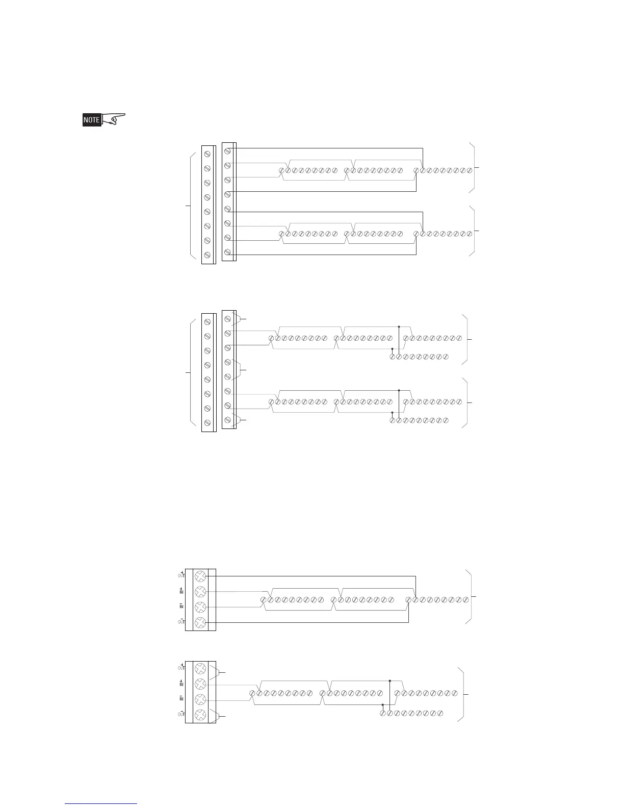
Device Loops (Figures 5 and 6)
The HZM communicates with the FireFinder-XLS via its DLC device loop. The device
loop may be wired Class A or Class B. Figure 5 shows both wiring types. Refer to the
DLC Installation Instructions, P/N 315-033090 for additional wiring information.
Do not mix wiring types; Zone 1 and Zone 2 must be the same wiring type.
NOTES
1. Loop resistance 50 ohms
Max with 252 devices on
the loop. Refer to the DLC
Installation Instructions, P/N
315-033090 if the number of
devices is less than 252.
2. Wire 18 AWG minimum, 12
AWG maximum.
3. No EOL device required.
4. Supervised, power limited to
NFPA 70 per NEC 760.
5. Positive and negative ground
fault detected at <60K ohms
for terminals 5-8 on HZM.
NOTES
1. Loop resistance 50 ohms
Max with 252 devices on
the loop. Refer to the DLC
Installation Instructions, P/N
315-033090 if the number of
devices is less than 252.
2. Wire 18 AWG minimum, 12
AWG maximum.
3. No EOL device required.
4. No jumper required between
terminal 1 and 2, terminal 3
and 4.
5. Supervised, power limited to
NFPA 70 per NEC 760.
6. Positive and negative ground
fault detected at <60K ohms
for terminals 5-8 on HZM.
LA
A
IN
TALLATI
N
NO T-TAPPING ALLOWED
CLASS B** INSTALLATION
T-TAPPING ALLOWED
*OPERATES IN FULL CONFORMANCE WITH STYLE 6 (ULC DCLA)
**OPERATES IN FULL CONFORMANCE WITH STYLE 4 (ULC DCLB)
1 2 3 4 5 6 7 8
9 10 11 12 13 14 15 16
1 2 3 4 5 6 7 8
9 10 11 12 13 14 15 16
CC-5/CC-2
CC-5/CC-2
ZON
2
ZONE
2
ZON
1
ZONE
1
NOT
USED
11 1
1
22 2
2
33 3
3
44 4
4
55 5
5
66 6
6
77 7
7
88 8
8
99 9
9
HZM
HZM
HZM
HZM
LINE 2
LINE 1
11 1
1
22 2
2
33 3
3
44 4
4
55 5
5
66 6
6
77 7
7
88 8
8
99 9
9
HZM
HZM
HZM
HZM
LINE 2
LINE 1
NOT USED
NOT USED
NOT USED
11 1
22 233 344 455 566 677 788 899 9
HZM
HZM
HZM
LINE 2 (RETURN)
LINE 2 (OUT)
LINE 1 (OUT)
LINE 1 (RETURN)
11 1
22 233 344 455 566 677 788 899 9
HZM
HZM
HZM
LINE 2 (RETURN)
LINE 2 (OUT)
LINE 1 (OUT)
LINE 1 (RETURN)
NOT
USED
CLASS A* INSTALLATION
NO T-TAPPING ALLOWED
CLASS B** INSTALLATION
T-TAPPING ALLOWED
*OPERATES IN FULL CONFORMANCE WITH STYLE 6 (ULC DCLA)
**OPERATES IN FULL CONFORMANCE WITH STYLE 4
ULC DCLB
ZONE
1
ZONE
1
11 1
1
22 2
2
33 3
3
44 4
4
55 5
5
66 6
6
77 7
7
88 8
8
99 9
9
HZM
HZM
HZM
HZM
LINE 2
LINE 1
NOT USED
11 1
22 233 344 455 566 677 788 899 9
HZM
HZM
HZM
LINE 2 (RETURN)
LINE 2 (OUT)
LINE 1 (OUT)
LINE 1 (RETURN)
Loop Circuit
FS-DLC Device
NOT USED
Loop Circuit
FS-DLC Device
NOTES
1. Loop resistance 50 ohms
Max with 252 devices on
the loop. Refer to the FS-
250 Installation, Operation
and Maintenance Manual if
the number of devices is
less than 252.
2. Wire 18 AWG minimum, 12
AWG maximum.
3. No EOL device required.
4. When wiring Class B, no
jumper required between
terminal +OUT and +IN,
terminal -OUT and -IN.
5. Supervised, power limited to
NFPA 70 per NEC 760.
6. Positive and negative ground
fault detected at <60K ohms
for terminals 5-8 on HZM.
Figure 5
HZM Device Loop Wiring Diagram For FireFinder-XLS
The HZM communicates with the FS-250 via its FS-DLC device loop. The device loop
may be wired Class A or Class B. Figure 6 shows both wiring types. Refer to the
FS-250 Installation, Operation and Maintenance Manual, P/N 315-049353, for addi-
tional wiring information.
Figure 6
HZM Device Loop Wiring Diagram For FS-250
 Loading...


