Siemens Industry, Inc.
Building Technologies Division
P/N 315-034850-85
1ELBAT
YTILIBITAPMOCMZH
snemeiS
rotceteD
ledoMesaB
noitallatsnI
snoitcurtsnI
H3/3-IDS3-BD91-349180-513
H3A/3A-IDS
3-BD91-349180-513
H3B/3B-IDI3-DA7-432390-513
11-TD11-BD
TPDA-BDhtiwS3-BD
5-924590-513
5-924590-513
121IHE11-BD,1
1-BDa_56318201V6A
121HOE11-BD,11-BDa_76318201V6A
121POE11-BD,11-BDa_76318201V6A
1911-ABP1911-BBP3-424590-513
T11
/11-EP11-BD
TPDA-BDhtiwS3-BD
P11-DA
01-891490-513
01-891490-513
11-956590-513
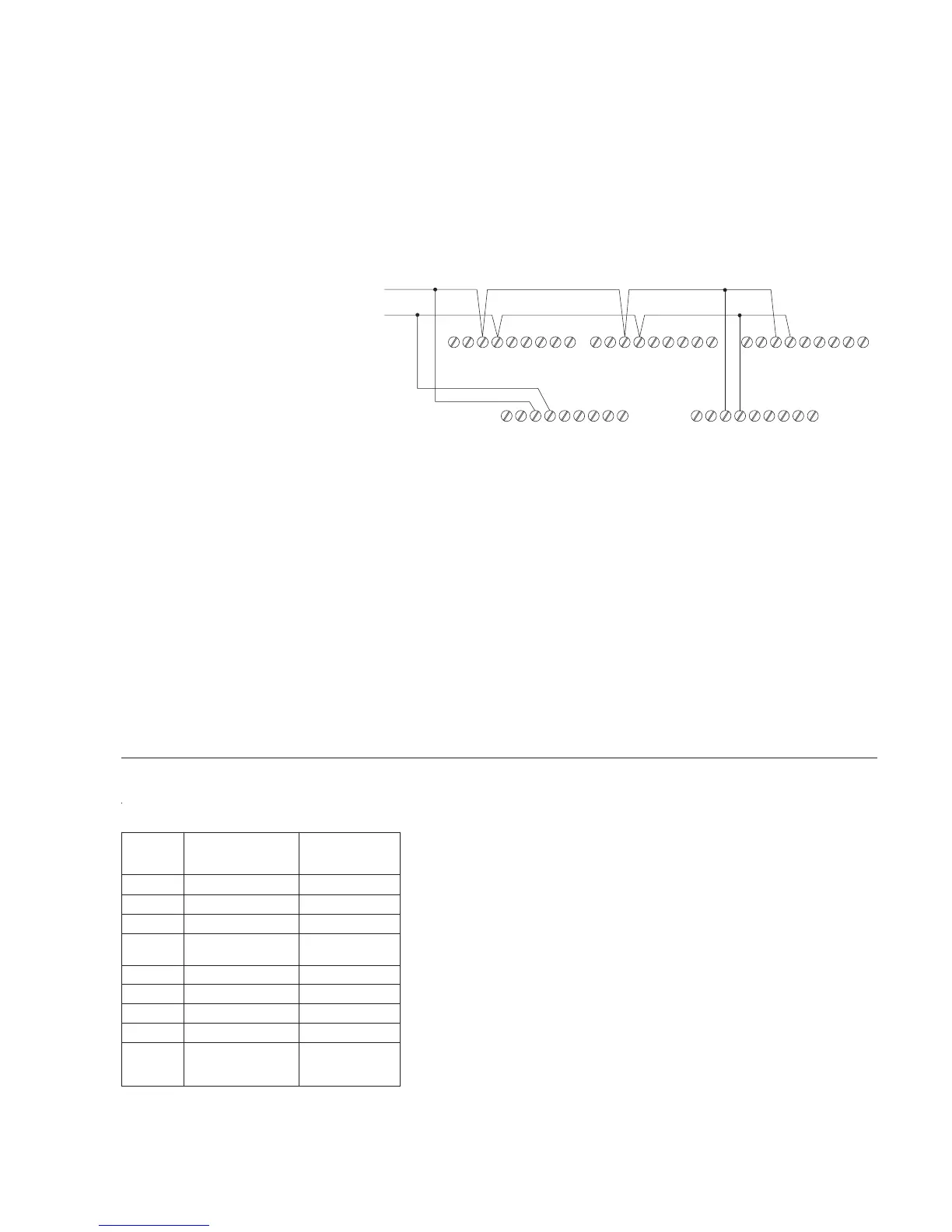
24 VDC Power (Figure 7)
In a FireFinder-XLS System, the HZM receives its power from the 24 VDC power
output on TB3 of the PSC-12 or PSX-12. In an FS-250 System, the HZM receives its
power from the 24V power output on the control panel or auxiliary power supply. The
24 VDC power may be wired only as Class B. Since the HZM monitors the power at
its screw terminals, you can star or T-tap the power connection. Refer to Figure 7 for
the wiring diagram.
1
11
11
22 2
22
33 3
3
3
44 4
4
4
55 5
5
5
66 6
6
6
77 7
77
8
8
8
88
9
9
9
99
HZM HZM HZM
HZMHZM
+
-
CLASS B INSTALLATION
T-TAPPING ALLOWED
TO 24 VDC
SEE NOTE 5
Figure 7
HZM 24 VDC Wiring Diagram
Mounting
1. Mount the HZM in a standard two gang electrical box. The box must have a
depth of at least 3½ inches.
2. When the field wiring for the initiating devices, device loop, and 24 VDC is
connected, press the HZM into the box and fasten it with the four screws
provided.
3. Attach a dress bezel if necessary, making sure that the ALARM LED is
aligned with the hole in the bezel.
COMPATIBILITY The devices in Table 1 are listed for use with the HZM.
• Use up to fifteen detectors, any combination of those listed.
• Only one PB-1191 (consisting of a PBA-1191 detector and PBB-1191
base), and no additional devices, can be connected to an HZM.
• Detector operated accessories cannot be used with the HZM.
• The model numbers listed are the UL compatibility identifiers.
NOTES
1. Wire 18 AWG minimum, 12
AWG maximum.
3. No EOL device required.
4. Supervised, power limited to
NFPA 70 per NEC 760.
5. A power supply which is
resettable, power limited
and UL listed for fire
protective signaling use and
is rated between 18.8-28.2
VDC.
6. Positive and negative ground
fault detected at <60K ohms
for terminals 5-8 on HZM.
 Loading...


