GAMMA instabus
Release: February 2012
KNX EIB TP-UART 2-IC
Technical Manual pages 42 Siemens AG
Infrastructure and Cities Sector,
Building Technologies
page 6 © Siemens AG 2012 Control Products and Systems
Subject to change without further notice. P. O. Box 10 09 53,
D-93009 Regensburg
2 The ANALOG – PART
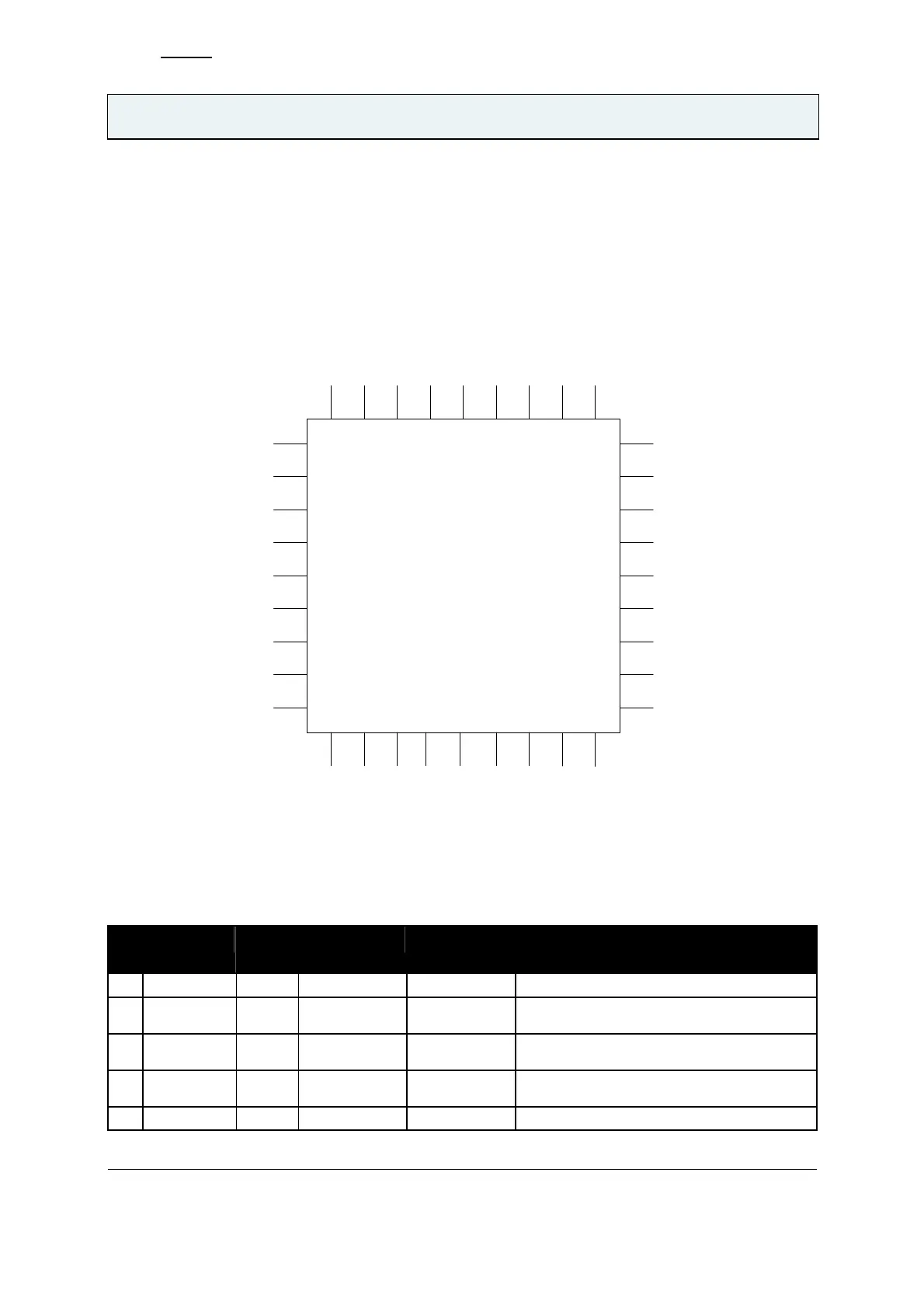
2.1 Package and Pin Definitions
2.1.1 Package Pin Assignment
NC0
1
R20
2
V20
3
VDDH
4
VSSH
5
SVCC
6
VCC
7
25
X1
24
TSTOUT_TW
23
TxD
22
21
20
RxIN
19
VSP
10 11
IND
12 13
BYP
14
VB
15
TxO
16
VDP
34 33 32 31 30 29 28
STxO
8
9
17
18
26
27
3536
TSTIN_BDS
TESTMODE
MODE 0
MODE 1
MODE 2
MODE 3
CTM
DIV
X2
V20PD
NC2
NC3
VB
VIF
SAVE
RxD
RESn
VB+
Figure 1 Package Pin Assignment
2.1.2 PIN DESCRIPTION
Pin
Pin Name Pin
Type
Positive supply
Negative
supply
Notes
1 NC0 AIO VB+ VB- Used during chip test mode
2 R20 AIO VDP VB- External resistor to VB- sets V20 max
current
3 V20 AIO 50V Clamp to
VB-
VB- Internally generated 20V power supply
4 VSP AIO 50V Clamp to
VB-
VB- Intermediate voltage blocking capacitor
5 VSSH AIO VSP VB- SMPS control