12/17
Building Technologies CC1N7761en
HVAC Products 19.02.2007
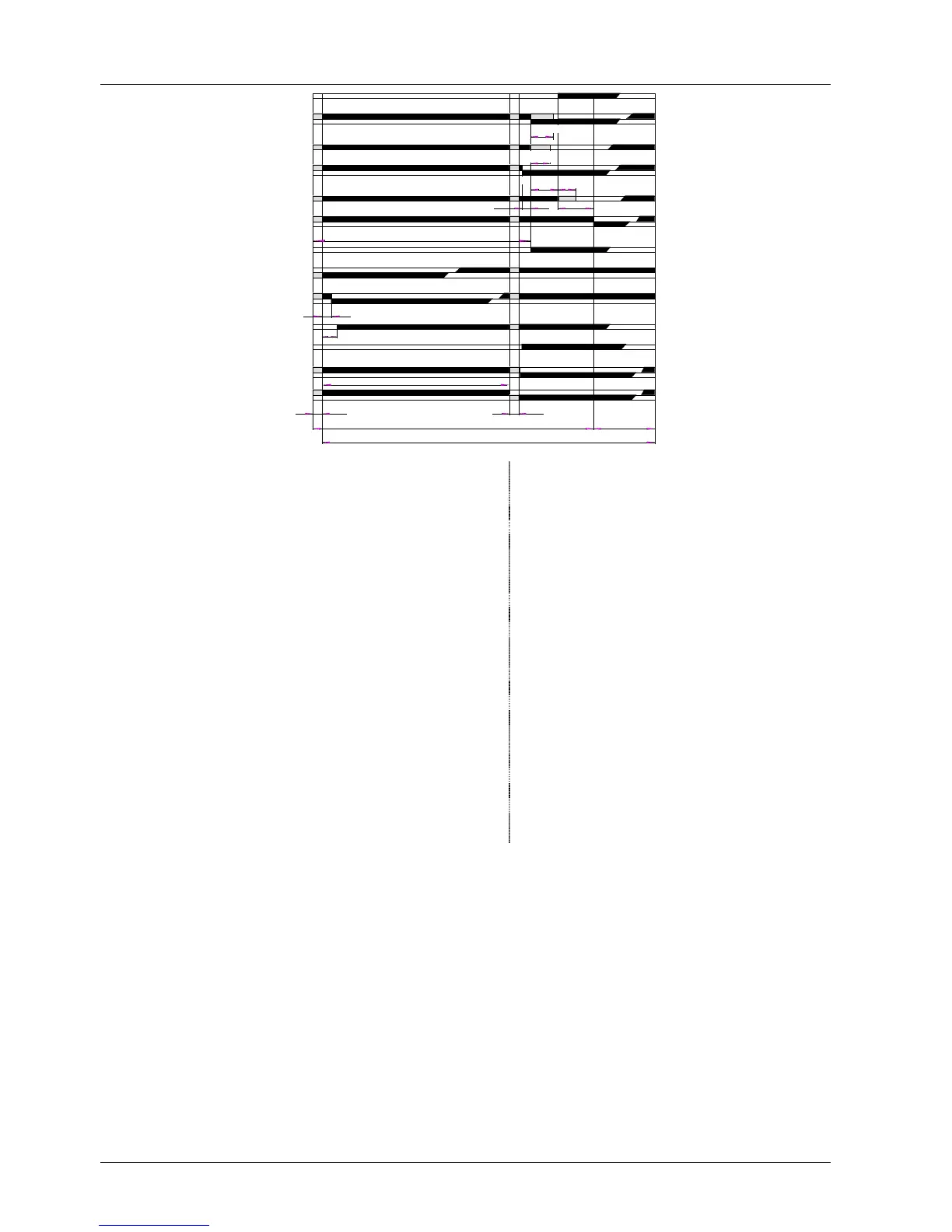
Sequence diagram of programming mechanism
t3
t7
t1 0
t1
t11
t8
T
t12
t6
TSA
t4 t9
t3´ t5
3
63
66
70
93
90
67
81
a
b
a
b
a
b
a
b
a
b
a
b
a
b
I
II
III
IV
V
VI
VII
VIII
IX
X
XI
XII
XIII
7761d01/0201
10
TSA´
79
Legend
AS Unit fuse LK Actuator with limit or auxiliary switches
AR Load relay with contacts «ar...» (refer so «Connection examples»)
BR Lockout relay with contacts «br...» a = actuator travels to the OPEN position
BV... Fuel valve (maximum air volume)
(BV...) Fuel valve for a pilot burner that is switched off on z = actuator travels to the CLOSED position
completion of the 2nd safety time (minimum air volume)
c... Fan contactor with contacts «c...» LP Air pressure switch
d... Auxiliary relay with contacts «d...» M... Fan motor, fan
e... Thermal cutout NTC Resistor with negative temperature coefficient
EK1 Lockout reset button on LEC1... OV... Oil valve
EK2 Remote lockout reset button Q Temperature or pressure sensor
ION Ionization probe QRA... UV detector
FR Flame relay with contacts R... Control thermostat or pressurestat
FW Contacts of flame safeguards LAE10..., LFE10... RAR... Selenium photocell detector
or LFE50... RV Control valve
GP Gas pressure switch SB Safety limiter
GV... Gas valve SM Synchronous motor of programming mechanism
H Main switch SQ... Type reference of air damper actuator
HR1 Auxiliary relay with contacts «hr11 / hr12» UL1 Operating switch for motor of programming mechanism
HR2 Auxiliary relay with contact «hr21» – can only be accessed after removal of housing cover
HR3 Auxiliary relay for flame detector or flame simulation UL2 Changeover link for «Short / long preignition time»
Test UL3 Changeover link for «STOP» or «Run» of the
L1 Lockout warning lamp, built-in programming mechanism after lockout
L2 Lockout warning lamp, external W Limit thermostat or pressure switch
L3 Signal lamp for flame indication Z Ignition transformer
Switching
T 120 s Run time of programming mechanism
times
TSA 0...9 s Ignition safety time (setting = 0 s in the case Ignition safety time of ignition spark proving)
TSA´ 0...6 s First safety time for the pilot burner in the case of startup with ignition spark proving
t1 8...63 s Adjustable prepurge time
t3 t11 + t1 + t12 + 7 s Long preignition time (during the entire prepurge)
t3´ 3 s Short preignition time
t4 11 s Interval between release of the 1
st
and 2
nd
fuel valve
t5 12 s Interval between release of the 2
nd
and 3
rd
fuel valve or the load controller
t6 T – (30 + t1) Postpurge time
t7 3 s Delay time
t8 t1 + 30 + t11 + t12 Total startup time startup sequence
t9 0...9 s 2nd safety time with interrupted pilot burner
t10 10 s Transition time - preset time for air pressure signal
t11 optional Programmed opening time for actuator «SA»
t12 optional Programmed closing time for actuator «SA»
For the factory setting of the different types, please refer to «Type summary».

 Loading...


