16/17
Building Technologies CC1N7761en
HVAC Products 19.02.2007
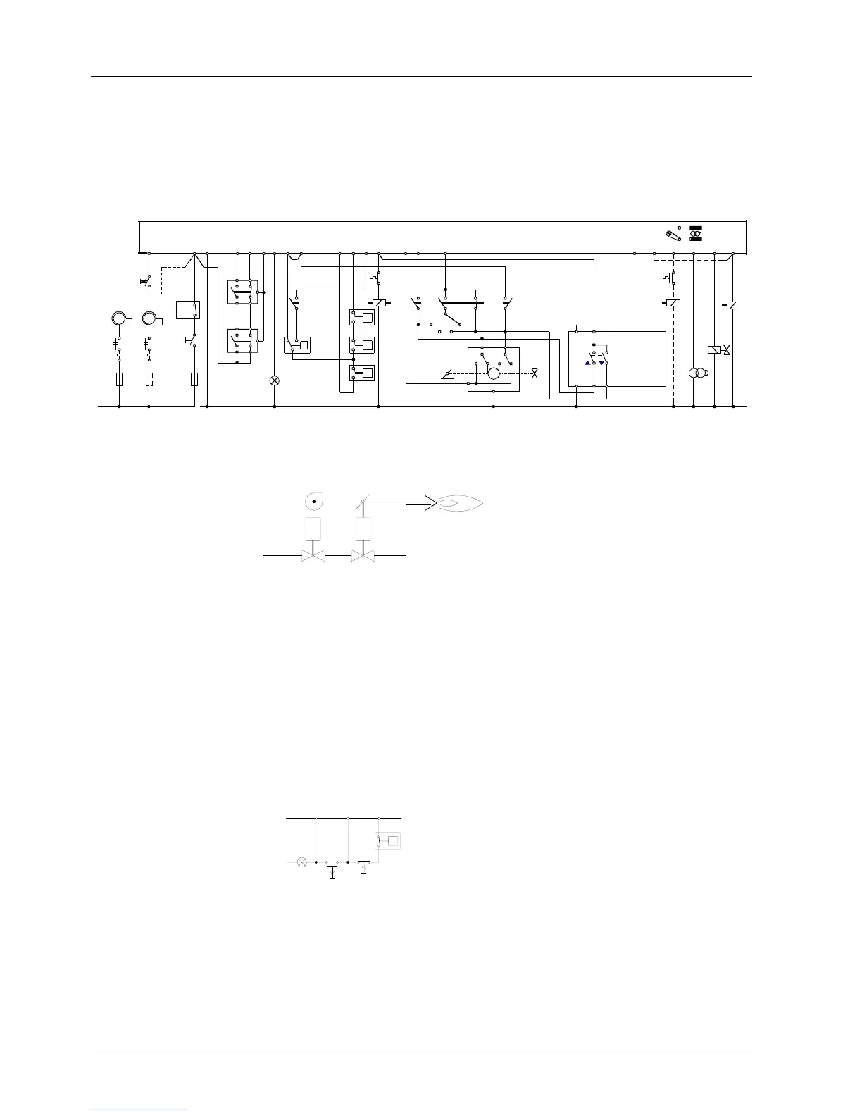
Connection examples and sequence diagrams (cont’d)
Double- or multiflame supervision of modulating burners
Including checked actuator control.
Required type of flame safeguards:
For oil LAE10 with active selenium photocell detectors RAR...
For gas LFE10 with UV detectors QRA... or ionization probe
For oil / gas LFE10 with UV detectors QRA...
1 2 13 14 15 12 19 18 8 9 4 3 20 22 21
d1c1
e1
c1
c1
10 11 17 6 5 7
e2
c2
d1
c1
H
M1
M2
MM
c1
e1
c2
e2
P
(R)
N
(Mp)
L2
P
LP
T
T
W
R
M
a
z
12
LK
11
12
N
RV
SQ...
Z
BV1
BS
I
II
III
IV
LEC1...
7761a10/0503
UL.2
EK2
16
3
7
4
5
6
FW
3
7
4
5
6
FW
(LAE10, LFE10)
P
GP
SB
**
*
RWF40
Q
L
NY1 Y2
* GP: Not required with oil burners
** LP: Recommended for oil burners, if the oil pump is not coupled to the fan motor
Operating switch BS1
I
Nominal load
II
Stop
III
Partial load
Air
Fuel
M
BV1
RV
SQ...
LK
7761a11e/0501
IV
Automatic control
Burners designed for continuous adjustment of the burner’s output (modulating burn-
ers) require the devices of the temperature or pressure control circuit, in addition to the
standard burner equipment, e.g.
1 Modulating controller RWF40...
1
Temperature or pressure sensor
QA... / QB...
1
Remote setting unit, if required
FZA...
1 Actuator for the control of the air damper and the fuel throughput
(fuel / air ratio control)
SQ...
1 Auxiliary relay d1
1 Operating switch BS
1 Control valve or similar for adjustment of the fuel throughput RV
18 8
9
L
N (Mp)
I
0
W
T
7761a07/0696
This circuit is used if, for certain reasons, fully automatic
operation is not required (e.g. with industrial burners).
The burner is started up by actuating impulse contact I; the
burner is shut down by either pressing circuit-breaking con-
tact 0 or when the limit thermostat cuts out.
Control for semiauto-
matic operating mode

 Loading...


