8/16 CC1N7421E December 04, 1998 Landis & Staefa Division
Operating voltage AC 230 V +10 % / -15 % Max. permissible cable lengths
QRA... to AGQ2...A27 20 m
Mains frequency 50 Hz -6 %...60 Hz +6 % (separate cable)
AGQ2...A27 to LMG2... 20 m
Environmental conditions
Transport
IEC 721-3-2 Weight
Climatic conditions class 2K2 AGQ2...A27 approx. 140 g
Temperature range -40...+60 °C QRA... refer to data sheet 7714
Humidity < 95 % r.h.
Mechanical conditions class 2M2 Mounting position optional
Operation
IEC 721-3-3
Climatic conditions class 3K5 Degree of protection IP 40
Temperature range -20...+60 °C
Humidity < 95 % r.h. Power consumption 4.5 VA
At mains voltage U
N
AC 220 V AC 240 V
Detector voltage at QRA... (with no load)
To the end of «t10» and after a controlled shutdown DC 400 V DC 400 V
From the beginning of «t1» DC 300 V DC 300 V
Detector voltage
Loading by DC meter Ri > 10 MΩ
To the end of «t10» and after a controlled shutdown DC 380 V DC 380 V
From the beginning of «t1» DC 280 V DC 280 V
DC current detector signals with UV detector QRA... min. required max. possible
Measurement made on UV detector 200 µA 500 µA
For UV detector QRA..., refer to data sheet 7712
Ancillary unit AGQ2...A27
When used in connection with burner controls LMG2..., the UV ancillary unit
AGQ2...A27 is required.
Using circuitry (A) or (B), the quench test on ageing UV detectors can be made in two
different ways:
Type of circuitry:
(A) Operation with a permanent line
• UV test at twice the supply voltage
across the UV cell on startup and after a
controlled shutdown
(B) Operation with a controlled line
•
UV test at twice the supply voltage on
startup only, during the interval between
controlled startup and air pressure signal
–
No voltage at the UV cell after a
controlled shutdown
–
No full substitute for mode (A)
described above since an aged UV cell
can regenerate itself
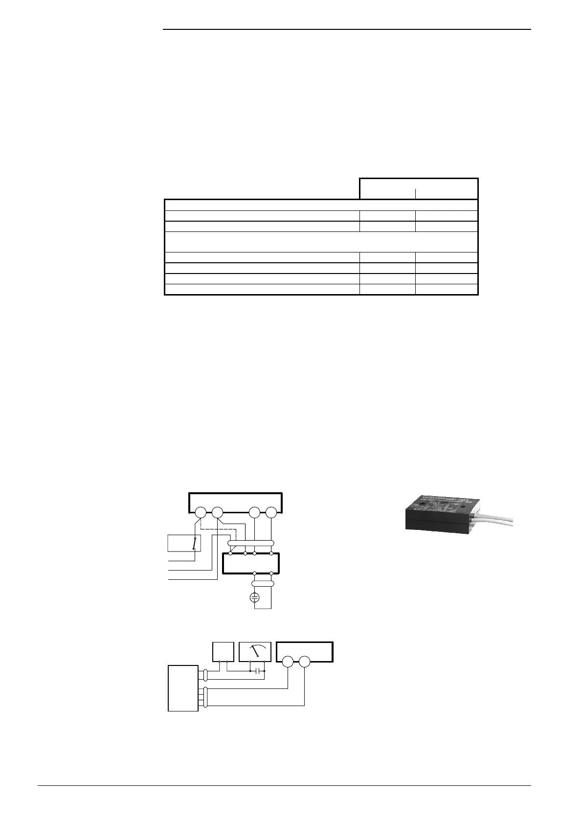
AGQ2.1A27
AQG2.2A27
Measurement made on UV detector
C Electrolytic capacitor 100...470 µF; DC 10...25 V
bl blue M Microammeter Ri max. 5000 Ω
sw black QRA... UV detector
gr grey
Flame supervision with
AGQ2...A27 and UV
detector QRA...
Legend
Connection diagram
12
2
11
*
1
7421a11/0598
GP/SB
R/W
L
L
N
QRA
+
-
br
bl
rt
sw
AGQ2...A27
sw
bl
(B)
(A)
LMG2...
Measurement circuit
AGQ2...A27
sw
bl
sw
bl
QRA
M
-
+
C
+
LMG2...
1
2
7421v02/0598
+
-
Legend
 Loading...
