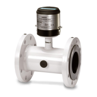
Do you have a question about the Siemens MAG 1100 and is the answer not in the manual?
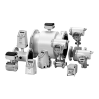
Explains the electromagnetic induction principle and transmitter/sensor components.
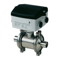
Provides technical specifications for MAG 1100 and MAG 1100 HT sensors.
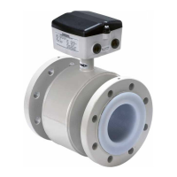
Lists technical specifications for the MAG 1100 F sensor.
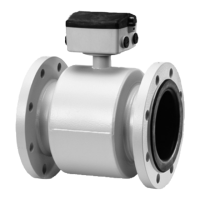
Details technical specifications for MAG 3100 series sensors.
Provides technical specifications for the MAG 5100 W sensor.
Outlines technical specifications for MAG 5000 and MAG 6000 transmitters.
Specifies the accuracy of the flowmeter for different models.
Table showing flow velocity, quantity, and sensor dimension relationship.
Table showing flow velocity, quantity, and sensor dimension relationship.
Details environmental and mounting conditions for correct installation.
Outlines ATEX directives and instrument categories.
Explains methods for achieving equal electrical potential between sensor and liquid.
Step-by-step guide for compact installation of MAG 5000/6000 transmitters.
Provides the wiring diagram for MAG 5000 and MAG 6000 transmitters.
Details wiring diagrams for transmitter and sensor connections.
Details the menu structure and modes for transmitter setup.
Details configuration of basic settings like flow rate and direction.
A checklist for troubleshooting transmitter issues.
Provides common troubleshooting steps for MAG transmitters.
A checklist for diagnosing MAG sensor problems.
| Type | Electromagnetic Flow Meter |
|---|---|
| Measurement Principle | Faraday's Law of Electromagnetic Induction |
| Pressure Rating | PN 16 |
| Lining Material | PTFE |
| Electrode Material | Stainless Steel, Hastelloy C |
| Output Signal | 4-20 mA, Pulse, Frequency |
| Power Supply | 24 V DC |
| Protection Class | IP67, IP68 |
| Material | Stainless Steel |
| Communication | HART, PROFIBUS PA |
| Medium Temperature Range | See Process Temperature |
| Ambient Temperature Range | -20°C to +60°C |
