EasyManua.ls Logo

Siemens MAMMOMAT - User Manual

Siemens MAMMOMAT
22 pages
Print Icon
To Next Page IconTo Next Page
Loading...
MAMMOMAT Balance
SP
The Maintenance Protocol
SPB7-115.832.01…
is required for this instruction
Maintenance Instructions
Print No.: SPB7
-
115
.
831
.
01
.
01
.
0
2
X
© Siemens AG 2004
The reproduction, transmission or
use of this document or its contents
is not permitted without express
w
ritten authority. Offenders will be
liable for damages. All rights,
including rights created by patent
grant or registration of a utility model
or_ design,_are_ reserved.
English
Doc. Gen. Date: 05.04
Question and Answer IconNeed help?

Do you have a question about the Siemens MAMMOMAT and is the answer not in the manual?

Summary

General Information

Training Requirements

Details on self-instruction packets or training workshops and required installation experience.

Required Documents List

List of essential documents for maintenance, including guides, diagrams, and protocols.

Tools and Measurement Devices

List of necessary tools, measurement devices, and auxiliary equipment for maintenance.

Required Lubricants

Specification of lubricants required for performing maintenance procedures.

Text Emphasis and Warnings

Explanation of text emphasis styles (DANGER, WARNING, CAUTION, NOTE) and their meanings.

Safety Information and Precautions

Crucial safety information and preventive measures to ensure safe maintenance operations.

Explanation of Abbreviations

Definitions for abbreviations used throughout the maintenance manual.

Document Symbols Guide

Explanation of symbols, including the radiation warning symbol, used in the document.

System Overview and Checks

Radiation Protection Checks

Inspect radiation protection shield for damage and verify legibility of lead equivalent value.

Mechanical System Integrity

Check C-Arm, tube cover, and table retain for damage, wear, and looseness.

Cable and Rotation Movement Tests

Inspect power cable condition and verify smooth rotation movement of the C-Arm.

Column Stand Maintenance

C-Arm Carriage and Drive Component Checks

Inspect C-Arm wheels, rails, gas spring, and vertical drive for damage/wear.

Limit Switch Functionality Test

Test limit switches for proper carriage stopping and blocking during vertical travel.

Vertical Travel Smoothness Verification

Ensure the vertical travel of the column stand is smooth and noiseless.

Compression System Procedures

Compression Plate and Support Inspection

Inspect compression plates for damage, wear, fixation, and support integrity.

Compression Force and Thickness Calibration

Test compression/decompression force and verify compression thickness display.

Foot Pedal Switch Functionality Test

Verify the proper functionality of each foot pedal switch.

Rotating Anode Starter Maintenance

Protection Circuit Verification

Check the protection circuit by initiating anode rotation in DEMO or manual modes.

Control LED Status Monitoring

Monitor control LED status for brake enabled states during rotation phases.

Brake Disabling for Heavy Use

Recommendation to disable anode rotation brake for heavy use to reduce temperature.

Filament System Checks

Anode Current Calibration Check

Perform anode current calibration check in manual mode with specific mAs values.

Filament Control LED Status

Monitor control LED status related to filament operation and X-ray exposure.

High Tension Power Supply Tests

kV Waveform and Internal kV Measurement

Analyze kV waveforms and perform internal kV measurement using test points.

External kV Check and Adjustment

Measure external kV, check adjustment points, and perform kV calibration.

HTPS Control LED Status

Verify HTPS Control LED status for fuse check and X-ray emission verification.

Miscellaneous Maintenance Procedures

Radiation Field and Light Field Testing

Test radiation field limitation as per Installation & Start-Up instructions.

AEC Detector Sensibility Test

Perform AEC Detector Sensibility test [r] with specified system configuration.

Calculated Dose Test Procedure

Check calculated dose values against calibration reports per service instructions.

Table Functions, Safety Locks & Exposure Blocking

Verify table functions, safety locks, and exposure release blocking conditions.

Emergency STOP Functionality Test

Test Emergency STOP on each side to ensure complete unit shutdown.

Image Quality and Phantom Exposure Tests

Perform image quality tests and compare phantom exposures to archives.

Final Maintenance Tests

Operating Problems and Cover Securing

Check for operating problems and ensure all covers are fitted correctly.

Protective Conductor Test and Cleaning

Perform protective conductor test and clean unit/repair damaged paint.

Final Test Exposure Confirmation

Execute one final test exposure to confirm overall system functionality.

Changes to Previous Version

Overview

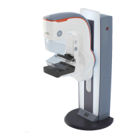
The provided document is a maintenance manual for the SIEMENS MAMMOMAT Balance SP mammography system. This manual, identified by Print No.: SPB7-115.831.01.01.02 and dated 05.04, outlines the procedures for preventive maintenance, safety inspections, and quality checks.

Function Description

The MAMMOMAT Balance SP is a mammography system designed for breast imaging. It incorporates a C-arm for positioning, a compression system for immobilizing the breast, an X-ray tube with a rotating anode, and a high-tension power supply to generate X-rays. The system includes various safety features and controls to ensure accurate and safe operation during examinations.

Important Technical Specifications

While the manual primarily focuses on maintenance, it provides insights into several technical aspects:

  • X-ray Tube: Features a rotating anode, with filament current calibration for both mAH and mAL.
  • High-Tension Power Supply: Operates within a range of 20 kV to 35 kV. The manual includes a conversion table for kV to VTP1/TP2 (±1%) on PCB 94-132, showing values from 279 Vdc at 20 kV to 488 Vdc at 35 kV. The kV waveform is designed to have no overshoot for any kV/mA loading factors.
  • Compression System: Supports magnification platforms at 1.5x and 2x. It allows for manual movement and includes a "Compression" force test and a "Decompression" force test.
  • Detectors: Utilizes AEC (Automatic Exposure Control) detectors, with a sensitivity test parameter [r].
  • Safety Features: Includes radiation protection shields, emergency stop buttons, and micro-switches for carriage travel limits. The system also has a "Dead Man" function for the X-ray pushbutton to prevent accidental triggering.
  • Software: Utilizes MAMMOMAT Balance SSW (Service Software Program) for service operations and includes logging of exposures/errors.

Usage Features

The manual highlights several operational aspects that are relevant to its usage:

  • Manual Mode: Allows for selection of specific mAs values (e.g., 40 mAs for 0.3 mm focus, 13 mAs for 0.1 mm focus) and kV settings.
  • AEC Calibration: Uses Plexiglas phantom blocks (2cm, 2cm, 2cm, 1cm, 0.5cm) for calibration.
  • Compression Thickness Display: Provides an indication of breast thickness, which is obtained by subtracting the F.F.D. (Film-to-Focal Distance) from the measured value.
  • Foot Pedal Switches: Used for various functionalities, including compression.
  • Collimation Plates: Supports 18x24 collimation plates.
  • Grid Table: Compatible with 18x24 grid tables.
  • Phantom Exposures: Used for image quality checks, comparing current exposures with archived starting values.
  • Zero Points Technique: A specific technique mentioned for image quality testing.

Maintenance Features

The core of the document details extensive maintenance procedures, categorized into Safety Inspections (SI), Electrical Safety Inspections (SIE), Mechanical Safety Inspections (SIM), Preventive Maintenance (PM), Preventive Maintenance Adjustments (PMA), and Preventive Maintenance, Function Check, Operating Value Check (PMF).

Key maintenance aspects include:

  • Required Documentation: Planning Guide, Wiring Diagrams, Installation and Start-up Instructions, Maintenance Protocol, Instructions for Use, and Service Instruction.
  • Required Tools and Devices: Oscilloscope, digital multimeter, non-invasive kVp-meter, dosemeter, service PC with software, SIB/Normi 7/customer phantoms, sensitometer/densitometer, protective conductor meter, bathroom balance, spray enamel, and standard installation tools.
  • Required Lubricants: All-purpose grease PD2 and Viscogen oil.
  • Safety Checks: Verification of radiation protection shields, C-arm attachment and handles, tube cover fixation, table retention, power connection cable condition, and foot pedal switches.
  • Mechanical Checks: Smooth and noiseless rotation movements, C-arm brake functionality, goniometer functionality, vertical travel of the column stand, and condition of C-arm carriage wheels, rails, gas spring assembly, chain, and gear box.
  • Electrical Checks: Functionality of limit switches (MW1, MW2, MW3, MW4), protection circuits for the rotating anode starter, and control LEDs on PCB 92-074.
  • Filament Current Check: Calibration modes for mAH and mAL, with parameters displayed on the mAs window.
  • High Tension Power Supply Checks: kV waveform analysis, internal kV checks using TP1/TP2 on PCB 94-132, and external kV checks using non-invasive instruments.
  • Miscellaneous Checks: Radiation field/light field limitation, automatic filter selection, RX signal lamp functionality, AEC detector sensitivity test, table functions and safety locks, blocking exposure release conditions, emergency stop functionality, exposure and error data recorder read-out, and deletion of exposure/error memory.
  • Quality Checks (QIQ, QSQ): Film O.D. linearity testing, image quality testing using phantoms, and system quality checks.
  • Final Tests: Removal of measurement devices, checking for operating problems, reattaching covers, protective conductor test, cleaning, and a final test exposure.
  • ESD Precautions: Emphasized for handling Printed Circuit Boards.
  • Radiation Safety: Explicit warnings for tests performed with radiation ON, requiring protective clothing.
  • Brake Disabling: Recommended for heavy use to reduce tube assembly temperature.

Siemens MAMMOMAT Specifications

General IconGeneral
BrandSiemens
ModelMAMMOMAT
CategoryScales
LanguageEnglish

Related product manuals