English 2. INSTALLATION – MICROMASTER Vector
G85139-H1751-U529-D1 © Siemens plc 199
4/8/99
20
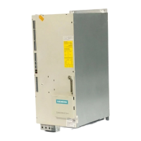
2.2.3 Power and Motor Connections - MICROMASTER Vector - Frame Size C
Figure 2.2.3: Power Connections Access Diagram - Frame Size C
: Fan housing opening tab
B & C: Gland plate release tabs
D: Control cable input
E: Mains cable input
F: Motor cable output
G: Braking resistor/ DC link cable input
H
J
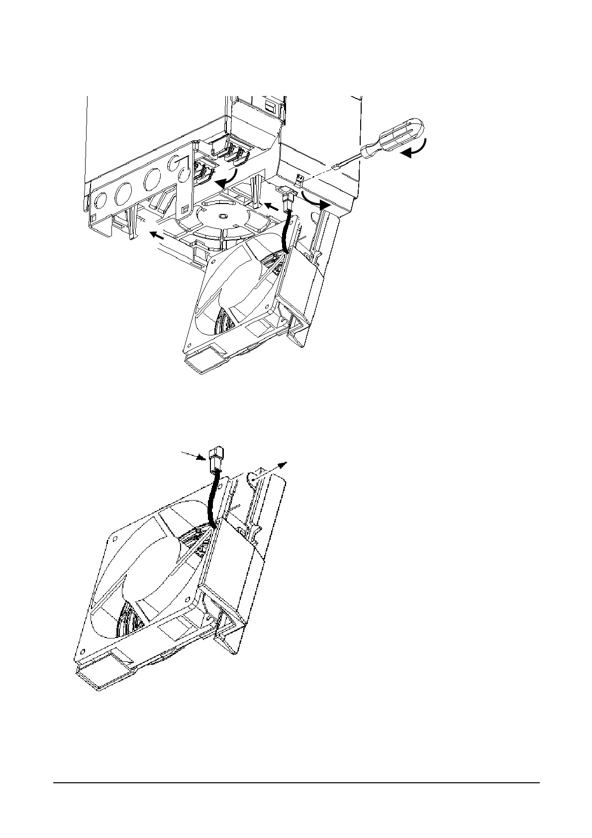
H: Fan connector
J: Fan Housing removal tab
To remove fan housing and fan disconnect fan
connector ‘H’, release tab ‘J’ in direction shown
and remove fan and housing in same direction.
G
F
E
D
B
C