EasyManua.ls Logo

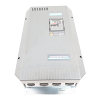
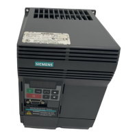
Siemens MICROMASTER Vector Series User Manual

Siemens MICROMASTER Vector Series
30 pages
To Next Page IconTo Next Page
Page #1 background imageLoading...
Page #1 background image
© Siemens plc 1999© Siemens plc 1999
G85139-H1751-U529-D1G85139-H1751-U529-D1
4/8/994/8/99
ContentsContents
SAFETY INSTRUCTIONS.............................................4SAFETY INSTRUCTIONS.............................................4
1. 1.
OVERVIEWOVERVIEW
.............................................................6.............................................................6
2. 2.
- -
MICROMASTER MICROMASTER
VectorVector
.........12.........12
3. 3.
INSTALLATION INSTALLATION
- -
MIDIMASTER MIDIMASTER
Vector..............Vector..............
2525
4. 4.
CONTROLS CONTROLS
AND AND
BASIC BASIC
OPERATION...............OPERATION...............
3232
5. 5.
OPERATING OPERATING
MODES...........................................36MODES...........................................36
6. 6.
SYSTEM SYSTEM
PARAMETERSPARAMETERS
.....................................41.....................................41
7. 7.
FAULT FAULT
AND AND
WARNING WARNING
CODES..........................65CODES..........................65
8. 8.
SPECIFICATIONSSPECIFICATIONS
................................................67................................................67
9. 9.
SUPPLEMENTARY SUPPLEMENTARY
INFORMATION....................73INFORMATION....................73
MICROMASTERMICROMASTER
VectorVector
MIDIMASTERMIDIMASTER
VectorVector
Operating InstructionsOperating Instructions
Question and Answer IconNeed help?

Do you have a question about the Siemens MICROMASTER Vector Series and is the answer not in the manual?

Siemens MICROMASTER Vector Series Specifications

General IconGeneral
Power Range0.37 kW to 250 kW
Storage Temperature-40 °C to +70 °C
Output Voltage0 V to Input Voltage
Frequency Range0 Hz to 650 Hz
Protection FeaturesOvercurrent, overvoltage, undervoltage, overload, short circuit, ground fault
CommunicationPROFIBUS, USS, Modbus RTU, CANopen
Cooling MethodForced air cooling
Relative Humidity95% (non-condensing)
AltitudeUp to 1000 m without derating
Enclosure RatingIP20, IP21, IP55 (depending on model)

Summary

Safety and Compliance Information

General Safety Warnings

Covers warnings about dangerous voltages, rotating parts, and qualified personnel.

Cautions and Usage Guidelines

Addresses public access, authorized use, and keeping operating instructions accessible.

Regulatory Compliance

Details compliance with Low Voltage, EMC Directives and UL/CUL certifications.

Important Operational Notes

Motor Operation and Parameter Setup

Crucial instructions for correct motor power selection and parameter entry before operation.

1. OVERVIEW

Product Features

Lists key capabilities, specifications, and optional features of the inverters.

1. OVERVIEW

1.1 Installation - General Notes

Covers environmental requirements for installation and ideal mounting.

Environmental Requirements

Details notes on temperature, altitude, shock, vibration, pollution, water, and overheating.

Ideal Installation Diagram

Visual guide illustrating proper mounting clearances and ventilation.

1. OVERVIEW

1.2 Wiring Guidelines to Minimise EMI

Provides best practices for wiring to reduce electromagnetic interference (EMI).

1. OVERVIEW

1.3 Electrical Installation - General Notes

General notes on electrical installation, including supply types and RCDs.

Operation with Unearthed (IT) Supplies

Specific operational notes for unearthed (IT) supply systems.

Operation with Residual Current Device (RCD)

Conditions and requirements for using Residual Current Devices (RCDs).

Installation after Period of Storage

Procedures for reforming capacitors after a prolonged storage period.

1. OVERVIEW

1.3.4 Operation with Long Cables

Guidelines and specifications for operating the inverter with long motor cables.

2. INSTALLATION – MICROMASTER Vector

2.1 Mechanical Installation

Safety warnings and general notes on the mechanical installation.

2. INSTALLATION – MICROMASTER Vector

2.1 Mechanical Installation

Details mounting requirements and fixing methods for frame sizes A, B, and C.

2. INSTALLATION – MICROMASTER Vector

2.1 Mechanical Installation

Presents mechanical installation diagrams and a table of frame size dimensions.

2. INSTALLATION – MICROMASTER Vector

2.2 Electrical Installation

Introduces electrical installation and shows connector layouts and wiring diagrams.

2. INSTALLATION – MICROMASTER Vector

2.2 Electrical Installation

Provides installation warnings, cautions, and details on cable connections.

2. INSTALLATION – MICROMASTER Vector

2.2.1 Power and Motor Connections - Frame Size A

Details the specific power and motor connections for MICROMASTER Vector Frame Size A.

2. INSTALLATION – MICROMASTER Vector

2.2.2 Power and Motor Connections - Frame Size B

Details the specific power and motor connections for MICROMASTER Vector Frame Size B.

2. INSTALLATION – MICROMASTER Vector

2.2.2 Power and Motor Connections - Frame Size B

Continues details for Frame Size B power and motor connections.

2. INSTALLATION – MICROMASTER Vector

2.2.3 Power and Motor Connections - Frame Size C

Details the specific power and motor connections for MICROMASTER Vector Frame Size C.

2. INSTALLATION – MICROMASTER Vector

2.2.3 Power and Motor Connections - Frame Size C

Continues details for Frame Size C power and motor connections.

2. INSTALLATION – MICROMASTER Vector

2.2.4 Control Connections

Details control terminal connections, DIP switches, and optional RS485.

2. INSTALLATION – MICROMASTER Vector

2.2.5 External Motor Thermal Overload Protection

Explains using a PTC temperature sensor for motor thermal overload protection.

2. INSTALLATION – MICROMASTER Vector

2.2.6 Block Diagram - MICROMASTER Vector

Presents a functional block diagram of the MICROMASTER Vector.

3. INSTALLATION – MIDIMASTER Vector

3.1 Mechanical Installation

Safety warnings and notes on mechanical mounting for MIDIMASTER inverters.

3. INSTALLATION – MIDIMASTER Vector

3.1 Mechanical Installation

Provides mechanical installation diagrams for MIDIMASTER Vector frame sizes.

3. INSTALLATION – MIDIMASTER Vector

3.1 Mechanical Installation

Presents a table of MIDIMASTER frame sizes, dimensions, and notes.

3. INSTALLATION – MIDIMASTER Vector

3.2 Electrical Installation

Details the electrical installation and shows connector layouts for MIDIMASTER Vector.

3. INSTALLATION – MIDIMASTER Vector

3.2.1 Power and Motor Connections

Describes the power and motor connections for MIDIMASTER Vector.

3. INSTALLATION – MIDIMASTER Vector

3.2.2 Control Connections

Details the control terminal connections for MIDIMASTER Vector.

Related product manuals