G85139-H1751-U529-D1G85139-H1751-U529-D1
© Siemens plc 1999© Siemens plc 1999
Wiring Guidelines Wiring Guidelines
the Effects of the Effects of
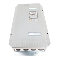
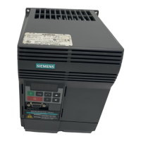
The inverters are designed to operate in an industrial environment where a high level of Electro-MagneticThe inverters are designed to operate in an industrial environment where a high level of Electro-Magnetic
Interference (EMI) can be expected. Usually, good installation practices will ensure safe and trouble-freeInterference (EMI) can be expected. Usually, good installation practices will ensure safe and trouble-free
operation. If problems are encountered, the following guidelines may prove useful. In particular, grounding ofoperation. If problems are encountered, the following guidelines may prove useful. In particular, grounding of
the system at the inverter, as described below, may prove effective. Figures 1.2.1-1.2.3 illustrate how an RFIthe system at the inverter, as described below, may prove effective. Figures 1.2.1-1.2.3 illustrate how an RFI
suppression filter should be installed and connected to the MICROMASTER Vector.suppression filter should be installed and connected to the MICROMASTER Vector.
common star point or busbar. It is particularly important that any control equipment that is connectedcommon star point or busbar. It is particularly important that any control equipment that is connected
to the inverter (such as a PLC) is connected to the same earth or star point as the inverter via a short,to the inverter (such as a PLC) is connected to the same earth or star point as the inverter via a short,
thick link. Flat conductors (e.g. braids or metal brackets) are preferred as they have lower impedancethick link. Flat conductors (e.g. braids or metal brackets) are preferred as they have lower impedance
at high frequencies.at high frequencies.
The return earth from motors controlled by the inverter should be connected directly to the earthThe return earth from motors controlled by the inverter should be connected directly to the earth
connection (PE) on the associated inverter.connection (PE) on the associated inverter.
good electrical connection is made between the heatsink and the panel, removing paint if necessary.good electrical connection is made between the heatsink and the panel, removing paint if necessary.
the cable neatly, ensuring that unscreened wires are as short as possible. Use cable glands wheneverthe cable neatly, ensuring that unscreened wires are as short as possible. Use cable glands whenever
etc. If control and power cables cross, arrange the cables so that they cross at 90° if possible.etc. If control and power cables cross, arrange the cables so that they cross at 90° if possible.
or ‘flywheel’ diodes for DC contactors,or ‘flywheel’ diodes for DC contactors,
fitted to the coilsfitted to the coils
. Varistor suppressors are also effective. This. Varistor suppressors are also effective. This
is particularly important if the contactors are controlled from the relay on the inverter.is particularly important if the contactors are controlled from the relay on the inverter.
the cable glands.the cable glands.
Electro-magnetic Electro-magnetic
noise-sensitive noise-sensitive
environment, environment,
be used to reduce the conducted and radiated interference from the inverter. For optimumbe used to reduce the conducted and radiated interference from the inverter. For optimum
performance, there should be a good conductive bond between filter and metal mounting plate.performance, there should be a good conductive bond between filter and metal mounting plate.
(Fig.1.2.1), (Fig.1.2.1),
minimise emissions.minimise emissions.

 Loading...


