© Siemens plc 1999© Siemens plc 1999
G85139-H1751-U529-D1G85139-H1751-U529-D1
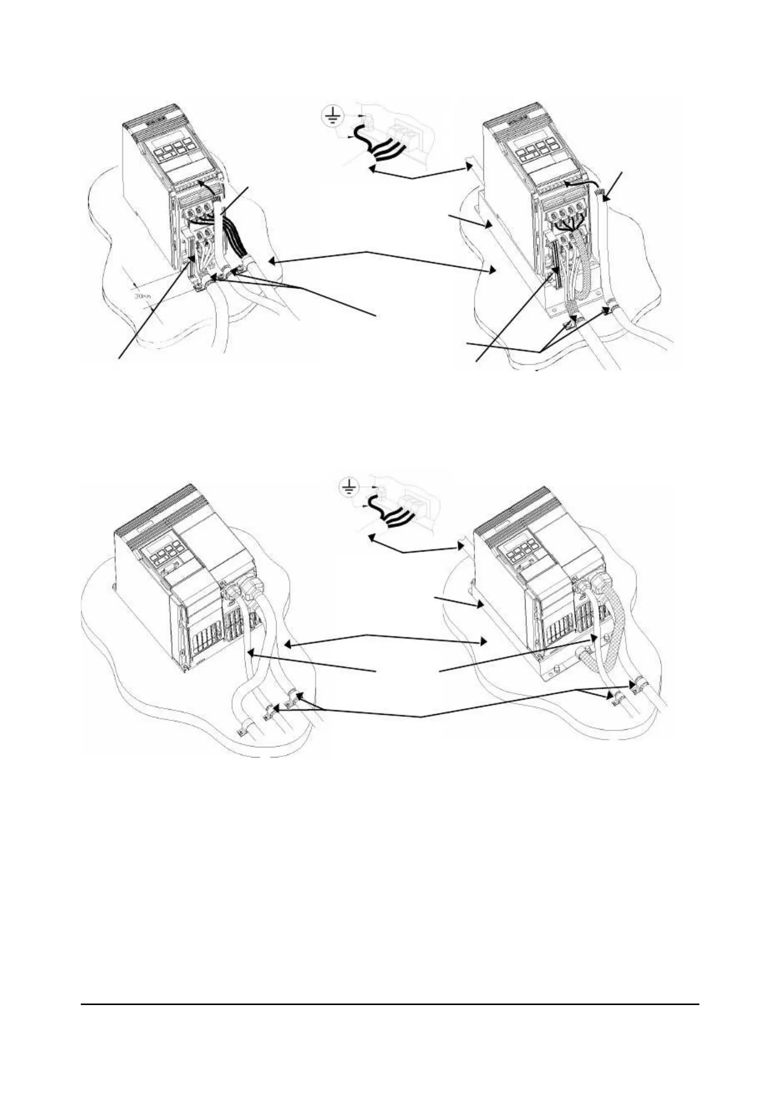
Figure 1.2.1: Wiring guidelines to minimise effects of EMI - MICROMASTER Vector Frame Size AFigure 1.2.1: Wiring guidelines to minimise effects of EMI - MICROMASTER Vector Frame Size A
Figure 1.2.2: Wiring guidelines to minimise effects of EMI - MICROMASTER Vector Frame Size BFigure 1.2.2: Wiring guidelines to minimise effects of EMI - MICROMASTER Vector Frame Size B
MAINS POWER INPUTMAINS POWER INPUT
METAL BACK-PLATEMETAL BACK-PLATE
FOOTPRINT FILTERFOOTPRINT FILTER
Fix motor and control cable screensFix motor and control cable screens
securely to metal back plate usingsecurely to metal back plate using
suitable clips.suitable clips.
MAINS POWER INPUTMAINS POWER INPUT
METAL BACK-PLATEMETAL BACK-PLATE
FOOTPRINT FILTERFOOTPRINT FILTER
Fix motor and control cable screenFix motor and control cable screen
securely to metal back plate usingsecurely to metal back plate using
suitable clips.suitable clips.