© Siemens plc 1999© Siemens plc 1999
G85139-H1751-U529-D1G85139-H1751-U529-D1
Read the Wiring Guidelines given in section 1.2 before commencing installation.Read the Wiring Guidelines given in section 1.2 before commencing installation.
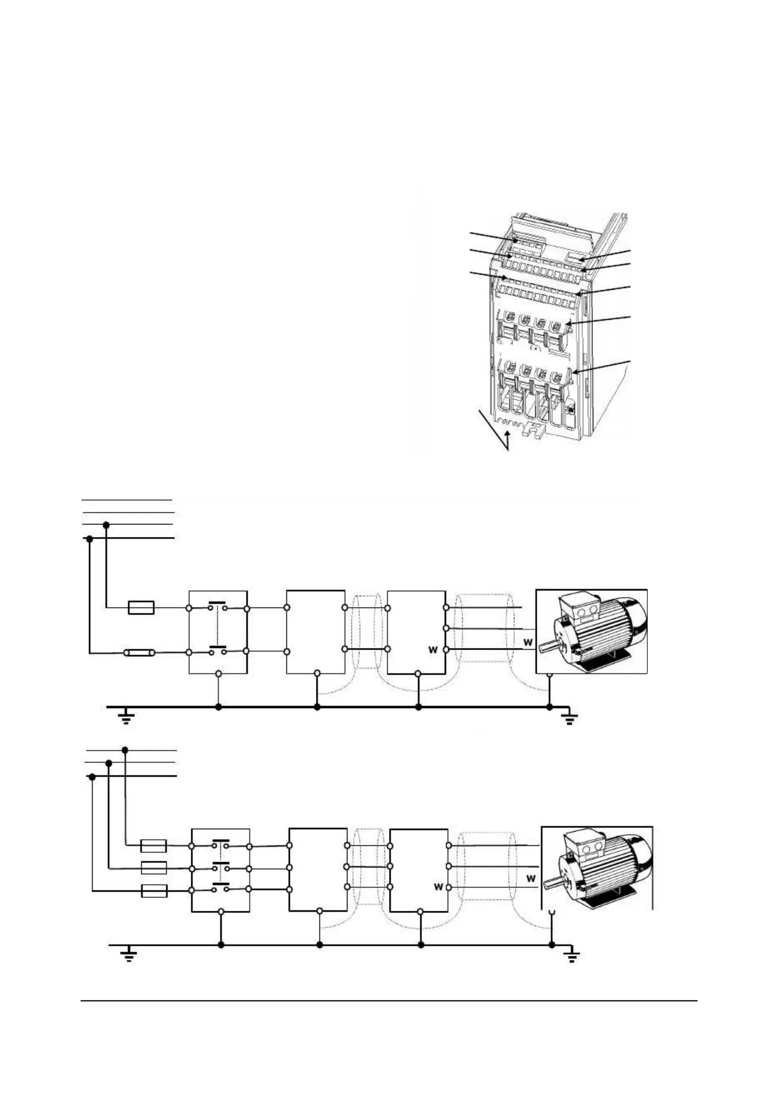
The electrical connectors on the MICROMASTER Vector are shown in Figure 2.2.1.The electrical connectors on the MICROMASTER Vector are shown in Figure 2.2.1.
Mains Input PowerMains Input Power
Motor TerminalsMotor Terminals
Brake TerminalsBrake Terminals
MICROMASTER VectorMICROMASTER Vector
MICROMASTER VectorMICROMASTER Vector
TYPICAL INSTALLATIONTYPICAL INSTALLATION
Figure 2.2.1: Figure 2.2.1:
MICROMASTER Vector Connectors MICROMASTER Vector Connectors
- Frame Size A- Frame Size A
Asynchronous and synchronous motors can be Asynchronous and synchronous motors can be
connected to theconnected to the
MICROMASTER Vector inverters either individually or in parallel.MICROMASTER Vector inverters either individually or in parallel.
If a synchronous motor is connected to the If a synchronous motor is connected to the
inverter, the motor current inverter, the motor current
and a half to three times greater than that expected, so, the inverter must be de-ratedand a half to three times greater than that expected, so, the inverter must be de-rated
accordingly. Also, the inverter cannot be used in vector mode when connected to aaccordingly. Also, the inverter cannot be used in vector mode when connected to a
synchronous motor (P077= 0 or 2).synchronous motor (P077= 0 or 2).