English 3. INSTALLATION – MIDIMASTER Vector
G85139-H1751-U529-D1 © Siemens plc 199
4/8/99
28
3.2 Electrical Installation
Read the Wiring Guidelines given in section 1.2 before commencing installation.
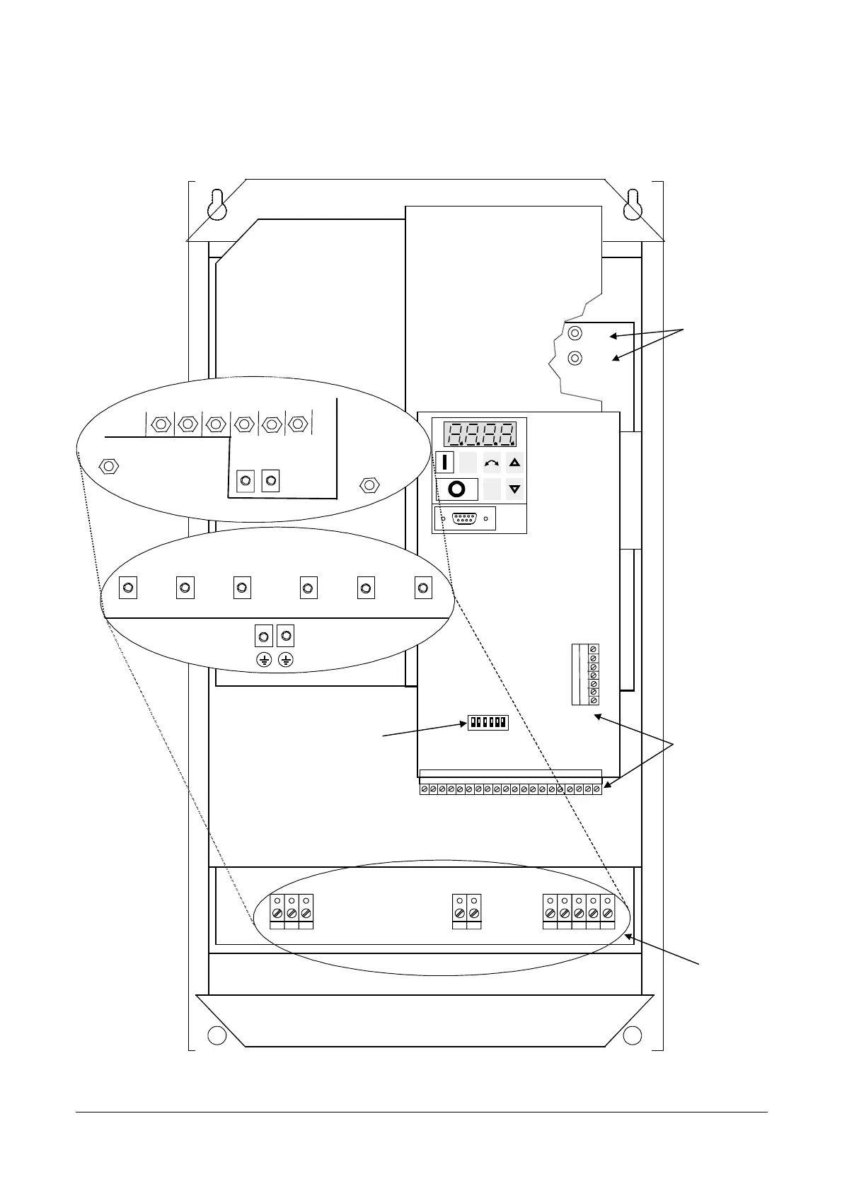
The electrical connectors on the MIDIMASTER Vector are shown in Figure 3.2.1.
DC+
DC-
DC-DC+ WL1 L2 L3 PE PE
2019181716151413121110987654321
L1 L2 WVUL3
VU
27
26
25
24
23
22
2
3
1
465
21
FS4/5 units
FS6 units
FS7 units
PE
V
U
L1
L2
L3
DC-
W
DC+
PE
FS6 units
Power and
Motor terminals
Control
terminals
DIP switches
Note:
Switch 6 not used
Jog
P
Figure 3.2.1: MIDIMASTER Vector Connectors