English 6. SYSTEM PARAMETERS
Parameter Function Range
[Default]
Description / Notes
G85139-H1751-U529-D1 © Siemens plc 199
4/8/99
54
P074 ·
I
2
t motor protection 0 - 7
[1]
Selects the most appropriate curve for the motor derating at low frequencies
due to the reduced cooling effect of the shaft mounted cooling fan.
0 = No derating. Suitable for motors with separately powered cooling or no
fan cooling which dissipate the same amount of heat regardless of speed.
1 = For 2 or 4-pole motors which generally have better cooling due to their
higher speeds. The inverter assumes that the motor can dissipate full
power at 50% nominal frequency.
2 = Suitable for special motors not continuously rated at nominal current at
nominal frequency..
3 = For 6 or 8-pole motors. The inverter assumes that the motor can dissipate
full power at nominal frequency.
4 = As P074 = 0 but the inverter trips (F074) instead of reducing the motor
torque / speed.
5 = As P074 = 1 but the inverter trips (F074) instead of reducing the motor
torque / speed.
6 = As P074 = 2 but the inverter trips (F074) instead of reducing the motor
torque / speed.
7 = As P074 = 3 but the inverter trips (F074) instead of reducing the motor
torque / speed.
Note: I
2
t motor protection is not recommended where the motor is lessthan half
the power rating of the inverter.
P075 ·
Braking chopper enable
(MMV only)
0 - 1
[0]
0 = An external braking resistor is not connected.
1 = An external braking resistor is connected.
An external braking resistor can be used to ‘dump’ the power generated by the
motor, thus giving greatly improved braking and deceleration capabilities. It
MUST be greater than 40W (80W for 3 AC 400 V inverters) or the inverter will
be damaged. Purpose made resistors are available to cater for all
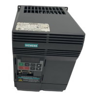
MICROMASTER Vector variants.
WARNING: Take care if an alternative resistor is to be used as the
pulsed voltage applied by the inverter can destroy
ordinary resistors.
I
N
= Nominal motor current (P083)
F
N
= Nominal motor frequency (P081)
P074 = 1/5 P074 = 3/7 P074 = 2/6P074 = 0/4
100% I
N
50% I
N
50% F
N
100% F
N
150% F
N
 Loading...


