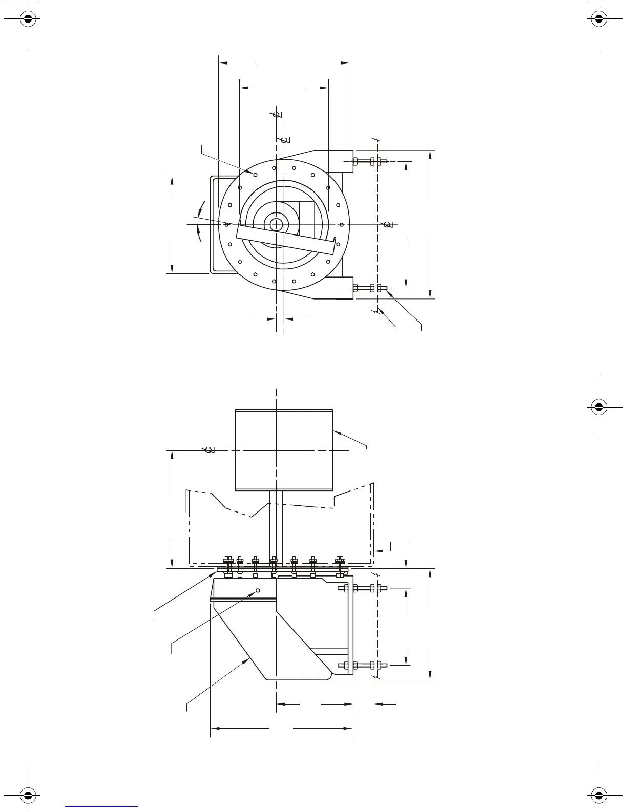
ILE - 61 Sensing Head Outline and Mounting
Notes:
1. Refer to Flowmeter drawing for sensing head mounting hole to flowguide centre line dimension.
2. Sensing head support plate should be rigid and independent of flowmeter housing.
3. Compress outer gasket to flowmeter sensing plate housing wall. Ensure that the outer gasket seal is dust tight.
outer gasket
conduit entry
½” NPT internal
fibreglass cover
560 mm
(22.05")
318 mm
(12.52")
60 mm
(2.36")
300 mm
(11.81")
420 mm
(16.54")
sensing
plate
see note 1
support plate
(by customer)
16 mm (0.63") dia.
(4 levelling rods)
560 mm
(22.05")
500 mm
(19.64")
490 mm
(19.29")
340 mm
(13.34")
380 mm
(14.96")
as req’d
8 mm (0.31" dia. 18 bolts
on 460 mm (18.11") BCD.
outer
gasket
sensing head
sensing plate
housing (see note 4)
7ML19985CX01.book Page 16 Thursday, September 18, 2003 12:15 PM