2 Using the MJ-4A & MJ-4B Operator Panel and Controls
Siemens Energy, Inc. 13
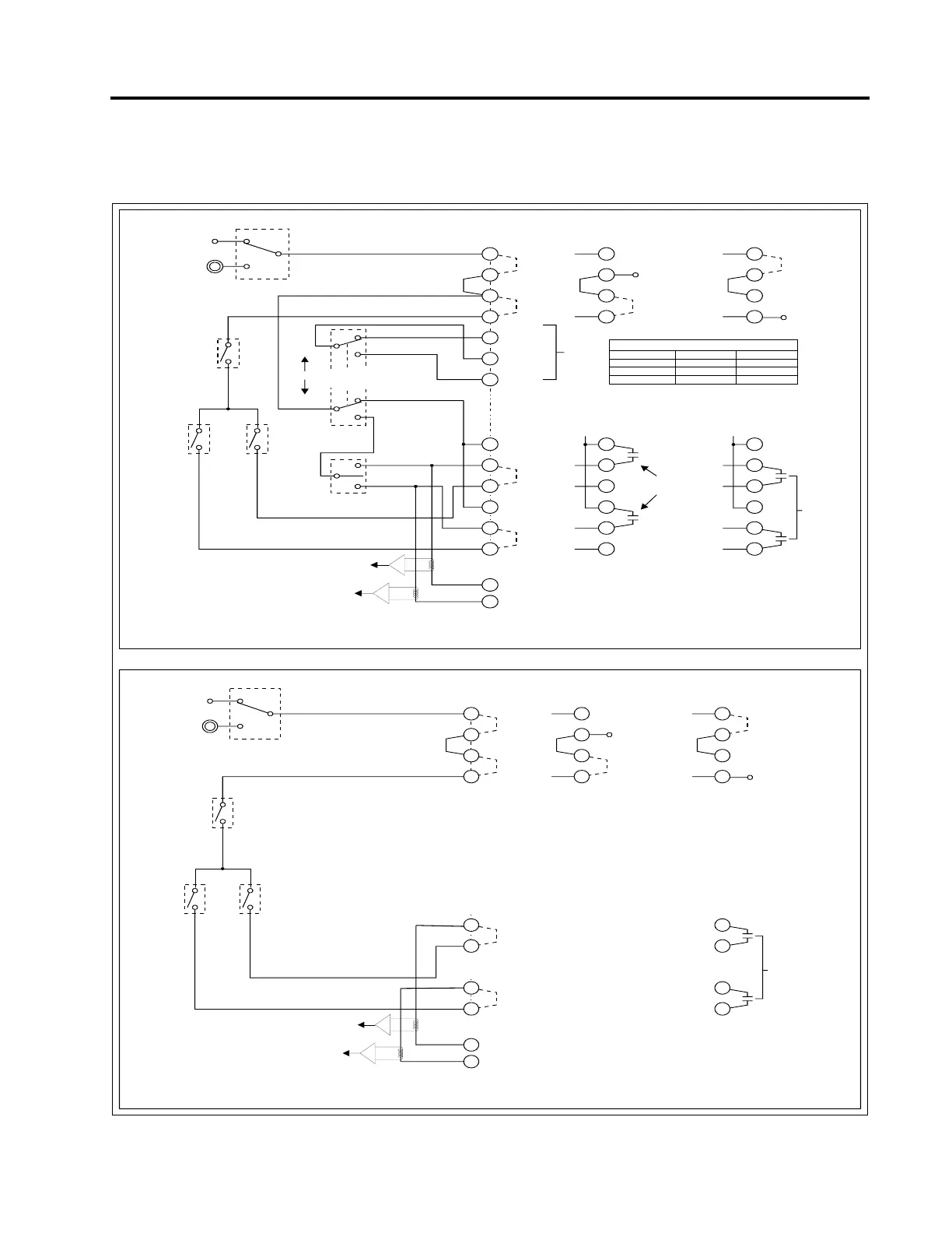
Power and Motor Control Terminal Contacts
A simplified schematic drawing of the power and motor control terminal connections is shown in Figure 2.3 below
.
Figure 2.4 Simplified Schematic of “Terminal” Remote Control Connections
Power Switch
On
External
PDS-U2
External
Source
(Line)
12 12 12
11 11 11
10 10 10
99 9
9
8
7
55 5
44 4
33 3
66 6
77 7
88 8
9
PDS-J
PDS-K
10
UP2B
P2B
P2B
P2B
P3A
P3A
P3A
P2B
P2B
P2B
P2B
P2B
P2B
P2A
P2A
UU
U6 U6 U6
U6 U6 U6
U7 U7 U7
REM-STAT
R/M Com
MAN-STAT
U-REM U-REM U-REM
Relay
Contacts
Open - Disable
Close - Enable
T.B.
Remote
Raise
Relay
Contacts
T.B.
Remote
Lower
J22 J22 J22
J21 J21 J21
U-REM U-REM U-REM
K22 K22 K22
K21 K21 K21
Remote/Auto/Manual
Switch
Manual
Tap
Raise/Lower
Switch
Manual
Remote
Raise
Off
Lower
"K" Current Sense
"J" Current Sense
Status
Outputs
Automatic
"Raise"
Relay*
K4
Automatic
"Lower"
Relay*
K5
Motor
Power
Control
Relay
K7
Connections for
External Motor Power
Connections for "Terminal Block" (T.B.) Remote Control
T.B. Remote Control for
R/A/M Switch in Remote
T.B. Remote Enable/Disable of
Automatic Operations
Connections for
External Motor Power
(Automatic Only)
External Power
(or connect
Relay between
U and U6)
External Power
(or connect
Relay between
U6 and U7)
Status of Remote/Auto/Manual Switch
REM to COM
Closed
Open
Open
Switch Position
Remote
Auto
Manual
MAN to COM
Open
Open
Closed
*Auto relays disabled when R/A/M
switch is in Manual position
Note: The dotted-lineconnections between terminals
represent the default (factory installed) jumpers.
Terminal Remote control connections for MJ-4A
Terminal Remote control connections for MJ-4B
Power Switch
On
External
PDS-U2
External
Source
(Line)
12 12 12
11 11 11
10 10 10
99 9
4 4
3 3
7 7
8 8
9
PDS-J
PDS-K
10
UP2B
P2B
P2B
P2B
P2B
P2B
P2B
P2B
P2A
P2A
UU
U6 U6 U6
U6 U6 U6
U7 U7 U7
Relay
Contacts
Open - Disable
Close - Enable
J22 J22
J21 J21
K22 K22
K21 K21
"K" Current Sense
"J" Current Sense
Automatic
"Raise"
Relay*
K4
Automatic
"Lower"
Relay*
K5
Motor
Power
Control
Relay
K7
Connections for
External Motor Power
Connections for "Terminal Block" (T.B.) Remote Control
T.B. Remote Enable/Disable of
Automatic Operations
Connections for
External Motor Power
(Autom atic Only)
External Power
(or connect
Relay between
UandU6)
External Power
(or connect
Relay between
U6 and U7)
*Auto relays disabled when R/A/M
switch is in Manual position
Note: The dotted-lineconnections between terminals
represent the default (factory installed) jumpers.
 Loading...


