4 Setting Up the MJ-4A & MJ-4B Control Panel
Siemens Energy, Inc. 37
4.8 Regulator Maintenance—
the <MAINTENANCE> Menu
The information contained within the <MAINTENANCE>
menu should be used for information purposes only. All
voltage regulator maintenance should be completed as
described in the Maintenance section of the Siemens Volt-
age Regulator Manual.
The <MAINTENANCE> Menu allows the user to enable
an algorithm which will approximate wear and tear on the
Tap changer contacts for Siemens Regulators. The menu
allows the user to chose a Tap Changer Type, indicate
presence of Balance winding and define the Range of
Regulation. The other items in this menu include items
which show statuses of the Tap changer contacts, and the
operations on the contact(s).
The statuses update based on the accumulated losses
due to wear and tear. The status are classified into EXCEL-
LENT, GOOD, WORN, and REPLACE. The Moving con-
tacts have a common status screen while the Stationary
contacts have one screen each.
The contact op counters update as operations are added
on the individual contacts.
The first screen in the <MAINTENANCE> menu is the
ConsOv screen which is a status screen, it shows the sta-
tus of the most worn contact(s).
Each of the individual contacts’ status or operations
maybe cleared by pressing the Cancel Reset button. If a
user wishes to clear all statuses and op counts at once
then this can be done by pressing Cancel-Reset key on
the ConsOv screen.
If the Maintenance approximation algorithm is disabled, all
statuses and contact op counts show “N/A”.. If the Main-
tainRcrds? data item is changed to “Y” then the algorithm
is enabled and would update the statuses and opcounts.
The Maintenance menu is password protected by default.
The default password of “3333” must be entered before
changing settings or resetting any statuses and contact op
counters.
The last screen in the maintenance menu is the OP_DUR
screen. This screen indicates the last measured op
counter pulse duration in seconds which is useful when
adjusting the TapInPulse time for TapIn=Pulse under
<Diagnostics> (i.e. the Tap Chgr is set to Custom or GE).
The Maintenance Menu also has a fast path key on the
front panel. Press this key to view the status and settings
screens of the Maintenance menu; repeat the key press
to scroll through the Maintenance menu.
4.9 Hardware Configuration—
the <DIAGNOSTICS> Menu
The <DIAGNOSTICS> Menu includes the MJ-4
hardware
configuration items in addition to the calibration and MJ-4
internal test items.
See Section 8 for information about the test and calibra-
tion items:
U2 Cal
P2 Cal
C/C2low
C/C2med
C/C2high
The MJ-4
provides three hardware configuration items to
assure compatibility between the MJ-4
electronics (hard-
ware) and the MJ-4
control program software. The hard-
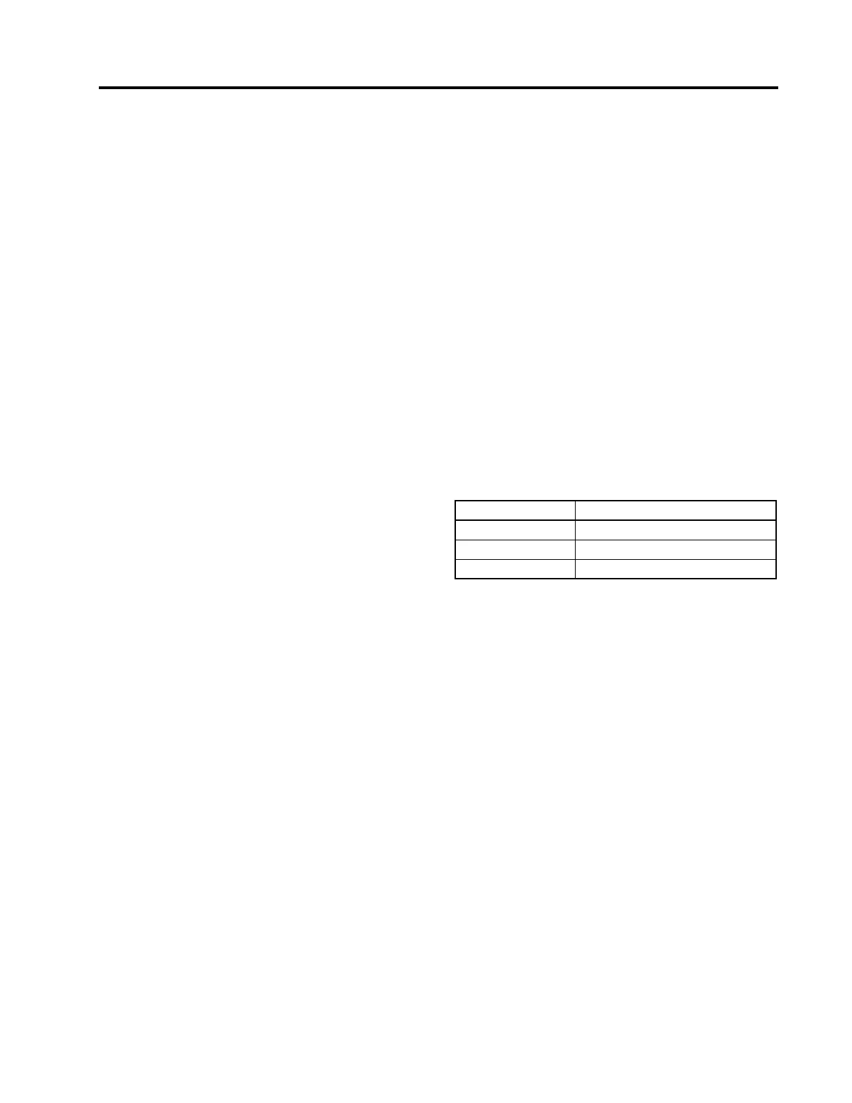
ware configuration items are listed in Table 4.11 below:
The Hardware configuration items are initialized at the fac-
tory. Normally, these items will not need to be changed or
updated.
For all MJ-4
units, the “MP MASK VERS:” item is factory
set. “0C” is the default setting and the operator/installer
should not change this value.
The <DIAGNOSTICS> Menu also includes the Serial
Number and Product Revision code for the MJ-4
Control
Panel. These are set at the factory and cannot be changed.
Refer to the Communications Module Instruction Manual
for information about the Comm Module items:
CM Test?
CM TestStat
The configurable tap changer control settings are also con-
tained in the <DIAGNOSTICS> Menu. Contact your Sie-
mens representative for more information before adjusting
these settings.
Table 4.11 Hardware Configuration Items
DATA ITEM DESCRIPTION
MP BD VERS: MJ-4
Main Processor Board Version
PWR BD VERS: For MJ-X Compatibility.
MP MASK VERS: MJ-4
Microprocessor Mask Version
 Loading...


