Appendix D: Menu Parameters
66 Siemens Energy, Inc.
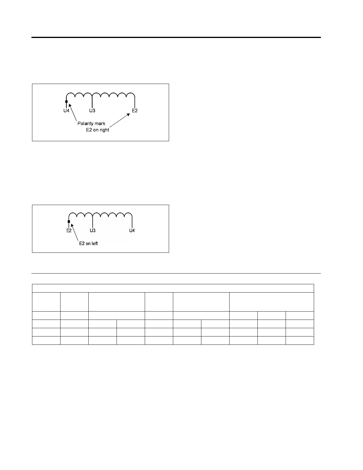
If the Un - - Ux taps are to the left of E2 with no taps to
the right of E2, and the polarity mark is on one of the
U taps, specify Utility Pol: NORM. (See Figure D.1.)
Figure D.1 Single-Phase Straight Design - Taps to the
Left of E2
If the Un - - Ux taps are to the right of the E2, and the
polarity mark is on the E2 tap, specify Utility Pol: REV. (See
Figure D.2.)
Figure D.2 Single-Phase Straight Design - Taps to the
Right of E2
D.3.1.3 Single-Phase Straight design regulators
(ANSI type A) with forced air cooling
For these regulators, the Utility winding not only provides
power to the controller — it also provides power for the
forced air fan(s). The E2 tap is located between the Un - -
Ux terminals on the regulator’s nameplate schematic. The
U5 tap is normally used for fan voltage and can be either
to the left or to the right of E2. To determine whether the
polarity is ‘normal’ or ‘reverse’, you must examine both the
schematic diagram and the connection table on the name-
plate. From the connection table, determine the tap to
which U2 should be connected.
• If the tap to which U2 is connected and the polarity
mark are to the left of E2 on the schematic, set Utility-
Pol:NORM.
• If the tap to which U2 is connected is to the right of
E2 on the schematic, set UtilityPol:REV.
Examples
For both of the examples on the next page, use the
nameplate connection table shown in Table D.3:
From the table, the system load voltage is 7200 volts; therefore, U2 would be connected to U6. Now check the connection
diagram:
Table D.3 Nameplate for Single-Phase Straight Regulator with Cooling Fan
Single Phase Straight Regulator with Cooling Fan
Load
Volts
+/-10%
Volt Tran
Sec Conn
P2 to
Control Panel P to
P14 to
Basis
Volts
Aux Volts Motor
Conn U2 to Volts
Fan Connection
U21 to U15 to Volts
14400 P3 - 120 20 20 120 U3 126 U3 U7 240
13200 P4 - 120 20 20 120 U4 126 U53 U7 242
7200 P5 - 120 20 20 120 U6 126 U6 U8 240
 Loading...


