Appendix K: Terminal Strip Connections
80 Siemens Energy, Inc.
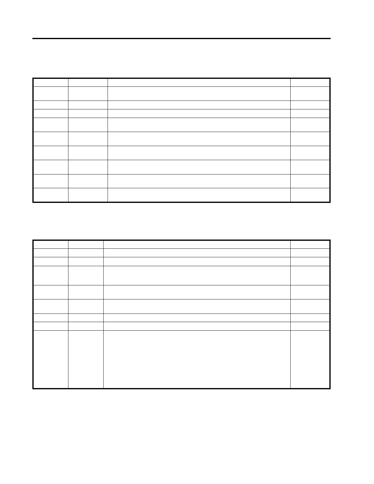
Table K.3 below describes the connections for terminal strip P3A
Table K.4 below describes the connections for terminal strip P3B
Table K.3 Connections for Terminal Strip P3A
Pin Number Signal Name Description I/O / Power
1 &2 INHIB OUT+
& INHIB OUT-
Inhibit Out is activated (closed) whenever the MJ-4 automatic mode operation is
inhibited by either the Automatic Inhibit Input or by Communication link.
Relay Output
3 AUXOUT C Common contact of Auxiliary Relay. Output
4 AUXOUT NO Normally-open contact of Auxiliary Relay. Output
5 & 6 AUXIN+
& AUXIN-
Auxiliary input contact pair. For future definition. Contact Closure
Input
7 MAN_STAT When closed to R/M COM it indicates that the MJ-4A is in the Manual Operating
Mode. The RA/O/M switch is in the Manual position. MJ-4A ONLY
Switch Closure
Output
8 R/M COM Common contact of the SPDT Remote-Automatic/Off/Manual (RA/O/M) switch.
[Use with Man_stat and Rem_stat.] MJ-4A ONLY
Switch Closure
Output
9 REM_STAT When closed to R/M COM it indicates that the MJ-4A is in the Remote Operating
Mode. The RA/O/M switch is in the Remote-Auto position. MJ-4A ONLY
Switch Closure
Output
10 & 11 ICIRC+
& ICIRC-
Reserved for Circulating Current Input signal pair. (0 - 640 mA, AC.) Current Input
12 P2SW P2 signal after the Power Switch. Used for externally monitoring the P2 voltage sig-
nal.
Output
Table K.4 Connections for Terminal Strip P3B
Pin Number Signal Name Description I/O / Power
1 J30 Spare connection for future application.
2 AUXOUT NC Normally-closed contact of Auxiliary Output Relay. (See P3A-3.) Relay Output
3 & 4 INHIB IN+
& INHIB IN-
INHIB IN directly disables the MJ-4 motor control relays. Through the microproces-
sor, this signal asserts Automatic Inhibit of motor Raise/Lower operations, and acti-
vates the Auto Inhibit Indicator.
Contact closure
(Input)
5 & 6 VRC1+
& VRC1-
These contacts are used to activate VRC (both MJ-3A
TM
mode and MJ-X
mode).
They are also used for External Line Drop Compensation Polarity Control.
Contact closure
(Input)
7 & 8 VRC2+
&VRC2-
These contacts are used to activate VRC Enable 2 for MJ-X mode. They are also
used for Alternate functions: Alternate Time Delay and Low External Battery.
Contact closure
(Input)
9 J412 Alternate signal source for “External Power” if jumper J9 is removed. See Table J.1.
10 C8_66A Reserved for future application.
11 & 12 C & C2 C & C2 (P3B-11&12) provide access to the regulator current path for connecting
auxiliary apparatus (e.g., an external current meter.) The current ranges from 0 to
640 mA nominal, into a low impedance load.
C&C2 have redundant jumpers. As shipped from the factory, there is a jumper
across the terminal strip pins, and there is an on-board jumper "J1".
[Both the terminal strip jumper and on-board jumper (J1) need to be removed if
external equipped is connected.]
Caution: Open circuiting the C&C2 connections may damage the regulator
Current Transformer (CT). Keep C&C2 shorted unless connected to an appro-
priate external current-handling device.
Current
 Loading...


