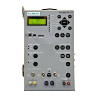
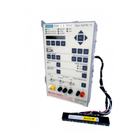
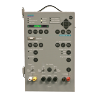
MJ-X Troubleshooting Guide AED-000025-04
Siemens T&D
LLC
3 version: 5 January 1998
MJ Simulator Voltage Source Connections:
Straight/Inverted
Switch
Inverted SSPT
Switch
“L” Voltage Source
Connection
“S” Voltage Source
Connection
Straight Doesn’t matter Jack plug “P2” Jack plug “U2”
Inverted INV SSPT Jack plug “U2” Jack plug “P2”
Inverted Off Jack plug “U2” none
Toggling the Power Flow Switch from Forward to Reverse changes the voltage-to-current phase
relationship from in-phase to 180° out-of-phase, respectively.
For tap motor direction sensing with the MJ-X, the MJ simulator must include load resistors (2.2K 10W)
from J to E and K to E. Check if your MJ simulator has these resistors. If your simulator lacks these
resistors, add them.
4. Jumper Tables
Make sure standard jumpers for both the power and main processor boards are in place for testing. See
tables below.
Power Board Jumper Table
Jumper
Designation
Jumper Connection Jumper
Type
Jumper
Location
Jumper Purpose
JP401 "+P" to "BAL" ("E" gnd) T.B. J405 1-2 For connecting balancing winding
JP402 "C" to "C2" T.B. J409 1-2 For connecting external current
meter
JP414 "U" to "U6" T.B. J405
10-11
For external control over tap motor
power signals
JP415 "U6" to "U7" T.B. J405
12-13
For external control of power for
MJ-X's (Auto) Tap Control Relays
JP416 "J21" to "J22" T.B. J405 4-5 For external control of (Auto) Raise
signal ("J") path
JP417 "K21" to "K22" T.B. J405 8-9 For external control of (Auto) Lower
signal ("K") path
(J402),
(J410)
External Source to Power
Switch
2 pin
header
J402,
J410
For connecting an external source of
"External Power" to SW403
(J408) (Version N power boards
only) Auto Inhibit Input:
pulsed or latched
3 pin
header
J408:2-3
(pre-prod.
default)
Auto Inhibit Input. For latched: use
J408:2-3. For pulsed: use J408:1-2.
(Version N power boards only)
 Loading...
