MJ-X Troubleshooting Guide AED-000025-04
Siemens T&D
LLC
4 version: 5 January 1998
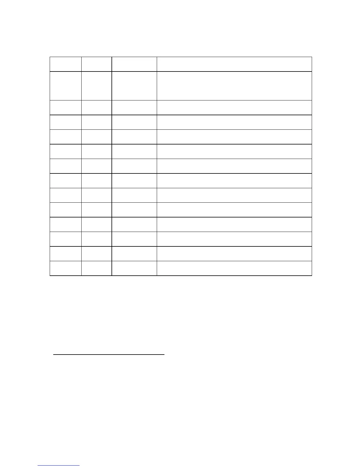
Main Processor Board Jumper Table
Jumper
Location
Jumper
Type
Jumper
Position
Jumper Purpose
J104 pins
6&8
part of 24
pin
header
IN (SW
Vers.2.03)
Out (SW
Vers.2.10 & up)
Connects DSACK0- to ground. (Indicates to uP that the data
bus is 8 bits rather than 16 bits.) This jumper needs to be
removed for connecting the test connector (J104) to the
Background Debug Mode (BDM) cable/interface.
J110 3 pin
header
2-3 1-2: For 128K x 8 Boot Flash device (28F001) at U2.
2-3: For 256K x 8 (any type) device (e.g., 28F020) at U2.
J111 3 pin
header
2-3 1-2: For 128K x 8 Boot Flash device (28F001) at U2.
2-3: For 256K x 8 (any type) device (e.g., 28F020) at U2.For
J113 3 pin
header
1-2 1-2: For 128K x 8 (or 32K x 8) Static RAM device at U3.
2-3: For 512K x 8 Static RAM device at U3.
J115 3 pin
header
1-2 1-2: Reset not asserted.
2-3: Reset asserted. (Connect this momentarily only.)
J116 2 pin
header
IN Connects D0 to pull down resistor. This connection is also
made with a trace on the circuit board for pre-production MP.
J117 2 pin
header
OUT Connects AGND to (digital) GND. Useful when testing MP
board by itself.
J118 2 pin
header
OUT Allows for a remote speaker to be used instead of the on
board speaker. (If remote used, remove on board speaker.)
J119 2 pin
header
OUT Connects (digital) GND to chassis, for protection.
J120 2 pin
header
IN For pre-production MP boards (version “0P”) only.
Connects data port connector shell to chassis, for protection.
J121 3 pin
header
1-2 1-2: For (local) data port wired as a "DCE".
2-3: For (local) data port wired as a "DTE".
J122 3 pin
header
1-2 1-2: For (local) data port wired as a "DCE".
2-3: For (local) data port wired as a "DTE".
J123 2 pin
header
IN For connecting DCE output handshake signals to local port
data connector (J106). (Out for DTE application.)
Unless otherwise noted, AC voltages are measured referenced to AC return ("E"). DC voltages are
measured reference to logic ground (GND). The logic ground is necessarily dc-isolated from the AC
return. Avoid connecting the logic ground to “E” or any other AC signals.
Note: The (local) data port should be jumpered as "DCE" for connecting to a terminal device (such as a
notebook or laptop computer) when using a straight-through cable. The (local) data port should be
jumpered as "DTE" for connecting to a modem when using a straight-through cable. Refer to MJ-X
Application Note 5 for further information.
5. Symptom Based Troubleshooting
Apply power and determine trouble symptom. Use Troubleshooting Symptom Tables below. [Find the
symptom that most completely describes what you are observing.]
Using MJXplorer, save the present MJ-X configuration and load “default” configuration.
To troubleshoot, use “known working” Power Board, Main Processor (MP) board, and MJ-X overlay. To
isolate faults, substitute the known good board/assembly. Make sure the "known good" board/assembly
has correct jumpering and configuration.

 Loading...


