EasyManua.ls Logo

Siemens MULTIMOBIL 2.5 - Service Manual

Siemens MULTIMOBIL 2.5
12 pages
Print Icon
To Next Page IconTo Next Page
Loading...
MULTIMOBIL 2.5
English
Print No.: SPR8-X01.831.01.02.02 Doc. Gen. Date: 09.05
Replaces: SPR8-X01.831.01.01.02
© Siemens AG 2003
The reproduction, transmission or
use of this document or its contents
is not permitted without express
written authority. Offenders will be
liable for damages. All rights,
including rights created by patent
grant or registration of a utility
model _or_ design,_are_ reserved.
SP
Maintenance Instructions

Other manuals for Siemens MULTIMOBIL 2.5

Question and Answer IconNeed help?

Do you have a question about the Siemens MULTIMOBIL 2.5 and is the answer not in the manual?

Summary

Maintenance Instructions

General

General safety and performance checks required every 12 months for proper operation and safety.

Replacing Damaged or Missing Screws

Instructions for replacing screws, emphasizing ESD regulations and specified screw tensile strength.

Cleaning

Guidelines for cleaning the unit safely, avoiding specific solvents, organic solvents, or spray methods.

Product Disposal

Legal regulations for product disposal and informing Siemens Customer Service to avoid environmental damage.

Electrolytic Capacitors Disposal

Instructions for emptying electrolytic capacitors and contacting customer service for proper disposal.

Mechanical Risk

Addresses mechanical risks, specifically the tension in the spring unit, and advises contacting customer service.

Safety Checks

User must follow daily and monthly safety checks to ensure proper functioning and safety.

Daily Safety Checks

Lists daily checks: power cord condition, exposure indicator, locking mechanism, and arm system position.

Monthly Safety Checks

Lists monthly checks: arm movements, locking lever function, and label legibility.

Performance Check (Every Six Months)

Six-month performance checks: counterbalancing, locking, brake, and sample exposure.

Aligning Light Field to Radiation Field

Procedure to align the light field to the radiation field, including operating sequence and adjustment evaluation.

Checking and Readjusting Counterweight

How to check and adjust the counterweight for smooth arm movements and proper positioning.

Adjusting Friction in the Arm

Instructions on adjusting the clamping knob for arm friction and tightening a related nut.

Removing the Top Panel

Steps to remove the top panel, including disconnecting power and securing the unit.

Removing the Front Cover

Steps to remove the front cover, including securing the unit and using soft bedding.

Removing the X-ray Source Assembly

Steps to remove the X-ray source assembly, including disconnecting power and securing movement.

Replacing the Single Tank

Procedure to remove and install a new single tank, including safety checks and connections.

Replacing the Collimator

Steps to replace the collimator, including disconnecting cables and removing screws.

Replacing the Collimator Lamp

Instructions for replacing the collimator lamp, including safety precautions and checking function.

Overview

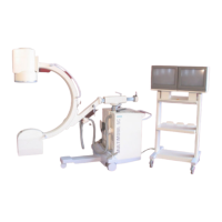
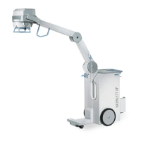
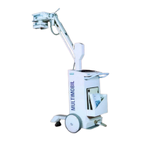
The Siemens Multimobil 2.5 is a mobile X-ray unit designed for diagnostic imaging. It is a versatile system, as indicated by its "Multimobil" designation, suggesting its capability to be moved and used in various locations within a medical facility, offering flexibility in patient care. The "2.5" likely refers to a specific model or version within the Multimobil series.

Function Description:

The Multimobil 2.5 functions as a complete X-ray imaging system, capable of generating X-rays, positioning the X-ray source relative to the patient and image receptor, and allowing for the acquisition of radiographic images. Its primary purpose is to provide diagnostic X-ray capabilities in situations where a fixed X-ray room is not available or practical, such as in operating rooms, intensive care units, emergency departments, or for bedside imaging. The system includes an X-ray tube assembly (referred to as a "Single Tank"), a collimator for shaping the X-ray beam, a support arm for positioning the X-ray source, a control panel for setting exposure parameters, and a mobile stand for portability. The unit is designed to be user-friendly, with features like counterbalancing for easy arm movement and a light field for accurate positioning.

Important Technical Specifications:

While detailed technical specifications like kVp, mAs ranges, or generator power are not explicitly listed in the provided excerpts, several key components and their characteristics are mentioned:

  • X-ray Tube Assembly (Single Tank): Contains the X-ray tube and transformer oil. The oil volume is approximately 3.2 kg, indicating a liquid-cooled or insulated X-ray tube, common for heat dissipation. The lead content for radioprotection is 1.65 kg, which is a critical safety feature.
  • Collimator: Also contains 1.65 kg of lead for radioprotection. It features a collimator lamp for light field indication, essential for accurate positioning of the X-ray beam. The collimator is adjustable to define the radiation field.
  • Capacitors: Electrolytic capacitors are present, with weights of approximately 1.5 kg and 5.5 kg. These are crucial components in the generator's power supply, likely for energy storage and smoothing.
  • Plastics: The system incorporates approximately 5 kg of PVC in cables and epoxy resin on PC boards.
  • Exposure Parameters: A sample exposure at 60 kV, 10 mAs is mentioned for performance checks, suggesting these are typical or testable exposure settings.
  • Radiation Field Alignment: The system allows for alignment of the light field to the radiation field, with a tolerance of ≤ 2.0 cm for both length (ΣY) and width (ΣX) deviations. This precision is vital for minimizing patient dose and ensuring image quality.

Usage Features:

  • Portability: The "Multimobil" name itself highlights its mobile nature, allowing it to be moved to different patient locations.
  • Control Panel: The unit has a control panel where the power switch is located and where exposure parameters are set.
  • Support Arm: A counterbalanced support arm facilitates easy and precise positioning of the X-ray source. It includes a locking mechanism to secure the arm in the desired position.
  • Collimator Lamp: A light field provided by the collimator lamp aids in accurate alignment of the X-ray beam with the area of interest on the patient.
  • Brake System: The unit is equipped with a brake (foot brake) to secure its position during exposure or transport.
  • Cassette Box: A cassette box is mentioned, indicating the use of film cassettes for image acquisition.
  • Safety Features: Includes an exposure indicator and an audible signal during exposure, as well as a radiation indication LED and a buzzer, all designed to enhance safety during operation.

Maintenance Features:

The manual provides comprehensive maintenance instructions, emphasizing safety and performance.

  • Regular Inspections: All parts and modules require testing and inspection every 12 months for performance and safety. More frequent inspections may be required by local regulations.
  • Screw Replacement: Damaged or missing screws must be replaced with specified steel screws (Nickel Plating 6492) to maintain structural integrity.
  • Cleaning Procedures:
    • The unit must be switched OFF and disconnected before cleaning.
    • Only water or a lukewarm mixture of household cleaner diluted with water should be used.
    • Abrasive cleaners, organic solvents (benzene, alcohol, spot removers), or disinfectant sprays are explicitly prohibited due to potential damage to materials, electrical components, or safety features.
    • Disinfectants should be aldehyde-based or ampholytic surfactant-based.
    • The room must be well-ventilated when using disinfectants.
  • Product Disposal: Special procedures are required for disposal due to hazardous materials (lead, transformer oil, electrolytic capacitors, plastics). Siemens Customer Service must be informed for proper disposal to prevent environmental damage or personal injury. Electrolytic capacitors must be emptied before disposal.
  • Mechanical Risk Mitigation: The tension in the spring unit (related to counterbalancing) must be relieved before certain maintenance tasks, and Siemens Customer Service should be informed.
  • Safety Checks:
    • Daily Checks: Power cord integrity, exposure indicator, audible signal, and locking mechanism for the support arm.
    • Monthly Checks: Lifting and lowering movements of the support arm, function of locking lever and cap screw on the X-ray tube, and legibility of labels.
  • Performance Check (Every Six Months): Counterbalancing of the support arm, locking mechanism, brake function, and verification of radiation indication LED and audio buzzer by taking a sample exposure (60 kV, 10 mAs).
  • Alignment Procedures: Detailed instructions for aligning the light field to the radiation field, including operating sequence, adjustment, and evaluation. This involves using a film cassette, radio-opaque markings, and adjusting collimator screws if deviations exceed 2.0 cm.
  • Counterweight Adjustment: Instructions for checking and readjusting the counterweight (spring tension) to ensure the support arm moves easily and stays in position. This involves tightening or loosening an M10 nut.
  • Friction Adjustment: Procedure for adjusting friction in the arm system using a clamping knob and a nut.
  • Component Removal/Replacement:
    • Top Panel, Front Cover, X-ray Source Assembly: Step-by-step instructions for safe removal, including disconnecting mains, lowering the X-ray source to transport position, applying brakes, and unscrewing fasteners.
    • Single Tank: Detailed procedure for replacing the X-ray tube assembly, including disconnecting connections, loosening bolts, and lifting the tank. A critical caution is provided: replacing the Single Tank necessitates recalibration of the equipment due to parameter adjustments and calibration being specific to the tank.
    • Collimator: Instructions for replacing a damaged collimator, including disconnecting cables and loosening screws. Requires subsequent light field to radiation field alignment.
    • Collimator Lamp: Procedure for replacing the lamp, including loosening a clamp screw. A caution advises against touching the glass envelope with bare fingers.

Overall, the Siemens Multimobil 2.5 is presented as a robust and maintainable mobile X-ray system, with a strong emphasis on safety, accurate operation, and structured maintenance protocols.

Siemens MULTIMOBIL 2.5 Specifications

General IconGeneral
BrandSiemens
ModelMULTIMOBIL 2.5
CategoryMedical Equipment
LanguageEnglish

Related product manuals