3.1.5 LON interface
3.1.5.1 PC/104 LON adapter
The NK822x processor board is equipped with a standard PC/104 interface for
system expansion. This is used for the LON add-on board.
Note: There are two revisions of LON interface boards, which have different LED
indications and different rotary switch settings.
Before checking the LEDs or setting the physical LON address with the rotary
switch, check the revision of the board you are using.
The 8-digit code (CD00251A or CD00251B) can be found on the rear of the
internal board in the upper left corner.
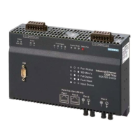
On the top of the NK822x module there are five LED’s and 1 push button.
NK822x LN board diagnostic LEDs
Blinking if LON is faulty
Blinking if LON is faulty
LED normally on, off when
receiving data
LED normally off, on when
receiving data
LED normally on, off when
transmitting data
LED normally off, on when
transmitting data
At the rear of the unit, there are 4 rotary switches for LON addressing (LON
physical address).

 Loading...