Introduction
2.1 Introduction
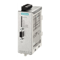
SIMATIC NET PROFIBUS, Optical Link Module
4 Operating Instructions, 07/2008, A2B00065774O, Edition V1.5
Every module has two (OLM P11, G11) or three (OLM P12, G12) independent channels
(ports) that consist of transmitter and receiver pairs.
The power supply voltage for operation is 24 V DC. To increase operational reliability, a
redundant power supply is possible.
The electrical channel is designed as 9-pin D-sub socket. An RS-485 bus segment
complying with PROFIBUS standard EN 50170 /2/ can be connected to this channel.
The fiber-optic cables are connected via BFOC
1
/2.5 connectors.
Six multicolor LEDs indicate the current mode and any disruptions as well as the level
ratios on the optical interfaces.
Table 2-1 shows the different connection options of the modules and the maximum
possible optical range of the single channels.
OLM/ P11 P12 G11 G12
G12-EEC
G11-1300 G12-1300
Number of channels
-electrical
-optical
1
1
1
2
1
1
1
2
1
1
1
2
Fiber types that can be used
- plastic fiber-optic cables
980/1000 µm
- PCF fiber-optic cables
(HCS
®
)
200/230 µm
- silica glass fiber-optic cables
10/125 µm (9/125µm)
50/125 µm
62.5/125 µm
80 m
400 m
-
-
-
80 m
400 m
-
-
-
-
-
-
3 km
3 km
-
-
-
3 km
3 km
-
-
15 km
10 km
10 km
-
-
15 km
10 km
10 km
Table 2-1 Number of electrical and optical ports per module,
usable fiber types, as well as maximum achievable fiber-optic cable distances between the modules.
See the “Technical Data” for precise conditions of use. PCF stands for Polymer Cladded Fiber and is
similar to HCS
®
2
.
There is a measurement output available for every channel, at which the optical input
level can be measured with a standard voltmeter.
The various error and disruption messages of the OLM are available as a group signal via
a signaling contact (relay with floating contacts) for further processing. The individual
modes as well as error/fault messages are displayed by several multicolor LEDs on the
front panel of the device (see section 5.7.1).
The mechanical design consists of a compact and stable metal housing which can be
mounted either on a DIN rail or on a mounting plate.
The modules are configured using switches that are easily accessible from the outside.
1
BFOC stands for Bayonet Fiber Optic Connector.
This type of connector is functionally compatible with ST connectors.
ST is a registered trademark of the company AT&T.
2
HCS
®
is a trademark of Ensign-Bickford Optics Company.
 Loading...