Product Characteristics
4.2 Installation
SIMATIC NET PROFIBUS, Optical Link Module
Operating Instructions, 07/2008, A2B00065774O, Edition V1.5
21
4.2.2 General information on commissioning
Unpack the OLM V4.0 and its accessories and check that the consignment is
complete and that there has been no damage during transportation. After
unpacking, the device should be acclimatized for some time to avoid condensation
after to storage in cold surroundings.
First choose the network topology suitable for your requirements. Commissioning
of the modules then involves the following steps:
¾ Checking and, if necessary, setting of the DIL switches.
¾ Installation of the modules.
¾ Connection of the power supply and, if required, connection of the signaling
contacts.
¾ Connection of the RS-485 bus line with installed bus connectors (if you use a
bus topology, remember that the terminating resistors in the connectors at both
ends of the line must be activated).
¾ Connection of the optical bus lines.
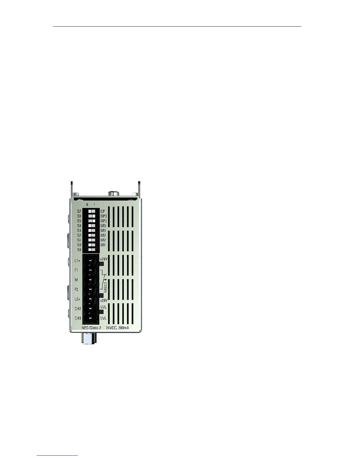
Figure 4-1 View of the OLM module from the top
Position of the DIL switches and of the terminal block for the power supply/signaling
contacts/level measurement. The figure shows the factory default setting of the DIL switches
(switches S0, S1, S2, S3, S4, S7 and S8 in position “0”, switches S5 and S6 in position “1”).
 Loading...