Product Characteristics
4.2 Installation
SIMATIC NET PROFIBUS, Optical Link Module
24 Operating Instructions, 07/2008, A2B00065774O, Edition V1.5
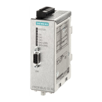
Mode “electrical channel without segment monitoring“
CH1 is set to this mode, when S0 is in position 1.
Note: This mode should only be set in the star segment of the star topology.
4.2.3.4 Setting the mode of the optical channels (CH2, CH3)
The mode can be set separately for each optical channel. Combinations of the
modes “bus with and bus without fiber-optic link monitoring” are possible.
Remember that the two optical channels connected via the fiber-optic cables must
always be set to the same mode! When operating with devices that do not provide
“fiber-optic link monitoring” this mode cannot be used and must be disabled on the
OLM V4.
If mode “redundant optical ring” is used, both optical channels have to be set to
this mode accordingly.
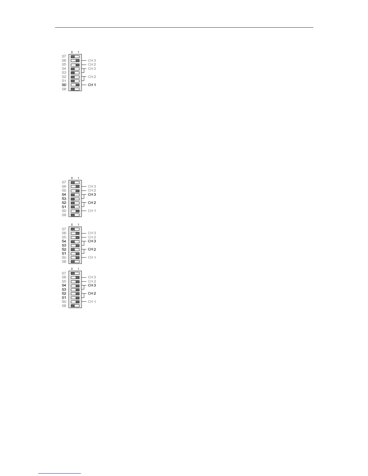
Mode “bus with fiber-optic link monitoring and segmentation”
CH2 is set to this mode, when S1 and S2 are in position 0.
CH3 is set to this mode, when S3 and S4 are in position 0.
Mode “bus without fiber-optic link monitoring”
CH2 is set to this mode, when S1 is in position 1 and S2 is in position 0.
CH3 is set to this mode, when S3 is in position 1 and S4 is in position 0.
Mode “redundant optical ring“
CH2 is set to this mode, when S1 and S2 are in position 1.
CH3 is set to this mode, when S3 and S4 are in position 1.
Note: Remember that both optical channels of a module must be set to the same
mode.
4.2.3.5 Reducing the optical transmit power for OLM/P11 and OLM/P12
Notice! The following information is only valid for the default setting of S7 (S7=0)!
The OLM/P11 and OLM/P12 have a high optical transmit power. Connecting these
modules with non-OLM devices via plastic fiber-optic cables can lead to optical
overdrive, especially if short cables are used. In this case, the optical transmit
power can be reduced by approx. 60% (3.8 dB).
The optical transmit power of CH2 is set with DIL switch S5.
The optical transmit power of CH3 is set with DIL switch S6.
S6 has no function for the OLM/P11.
 Loading...