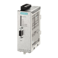
SIMATIC NET PROFIBUS, Optical Link Module
Operating Instructions, 07/2008, A2B00065774O, Edition V1.5
v
6.4 Ex approval ..................................................................................................................................47
6.5 UL approval (U.S. and Canada)...................................................................................................47
6.6 Shipbuilding approvals.................................................................................................................48
7 References .............................................................................................................................................. 49
7.1 References...................................................................................................................................49
8 Drawings.................................................................................................................................................. 51
Tables
Table 2-1
Number of electrical and optical ports per module, .......................................................................4
Table 4-1 Overview of the product characteristics.......................................................................................19
Table 4-2 DIL-switches in compatibility mode..............................................................................................23
Table 5-1 Meaning of the LED displays and indication by the signaling contact.........................................39
Table 5-2 Constants for calculating the slot time for DP-standard (redundant optical ring) ........................43
Table 5-3 Constants for calculating the slot time for DP/FMS (”universal“) and DP with S5 95U (redundant
optical ring)...................................................................................................................................43
Figures
Figure 2-1
PROFIBUS OLM with position of all interfaces, displays and adjustment options ........................3
Figure 3-1 Network structure in a linear (bus) optical topology.......................................................................8
Figure 3-2 Network structure with an optical star topology ...........................................................................10
Figure 3-3 Network structure with a redundant optical ring topology............................................................12
Figure 4-1 View of the OLM module from the top .........................................................................................21
Figure 5-1 Measures to suppress..................................................................................................................27
Figure 5-2 Securing shielded cables with cable clamps and cable retainers...............................................28
Figure 5-3 View of the module from below....................................................................................................30
Figure 5-4 Installation of a module on a standard DIN rail............................................................................31
Figure 5-5 Installation of a module with a mounting plate.............................................................................32
Figure 5-6 Drilling measures for the mounting plate, all dimensions are millimeter......................................33
Figure 5-7 Electrical port, connector assignment D-sub jack.......................................................................33
Figure 5-8 Operating power supply, pin assignment 5-pin terminal block ..................................................35
Figure 5-9 Signaling contact relay with floating contacts; ............................................................................35
Figure 5-10 Signaling contact, pin assignment 5 pin terminal block .............................................................35
Figure 5-11 Position of the level recording connections ................................................................................36
Figure 5-12 Relationship between measured output voltage and signal quality.............................................36

 Loading...


