1-1
Manual OP5, OP15
( ) J31069-D0840-U001-A2-7618
Product Description
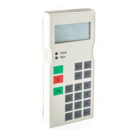
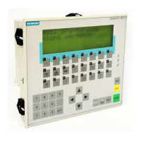
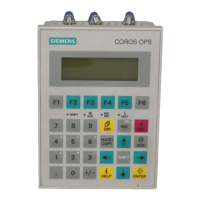
Operator Panels OP5 and OP15 allow operating states, current process values
and malfunctions of a connected PLC to be visualized. In addition, inputs can
be made on the OP which can be written directly to the PLC. Some functions
relating to machine diagnostics can also be executed on the Operator Panel.
The Operator Panels are suitable for fitting into switching cabinets and con-
trol desks. A printer can be attached to the OP for logging processes during
automation operation.
The Operator Panels feature a number of standard functions. The displays
and operation of the devices can be optimized by the configurer to meet the
requirements of the process.
1.1 Configuration and process control phases
Before an OP can go into service, it has to be prepared for its job of visualiz-
ing data from the PLC, i.e. it has to be configured. As far as the PLC is con-
cerned, data areas used by the OP to communicate with the PLC have to be
created in the memory.
The configuration for the OP is created on a computer (PC/PU) using Pro-
Tool/Lite configuration software under Microsoft Windows
TM
. When the
configuration is ready, it is transferred to the OP. Before this can be done,
however, the computer has to be connected to the Operator Panel. Following
transfer of the configuration, the OP has to be connected to the PLC.
The OP now communicates with the PLC and reacts to program flows on the
PLC on the basis of the configured requirements.
The following illustration depicts the configuration and process control
phases de scribed above:
Applications of
OP5 and OP15
Creating data
areas
Configuration with
ProTool/Lite
1
 Loading...