8
28 | 30
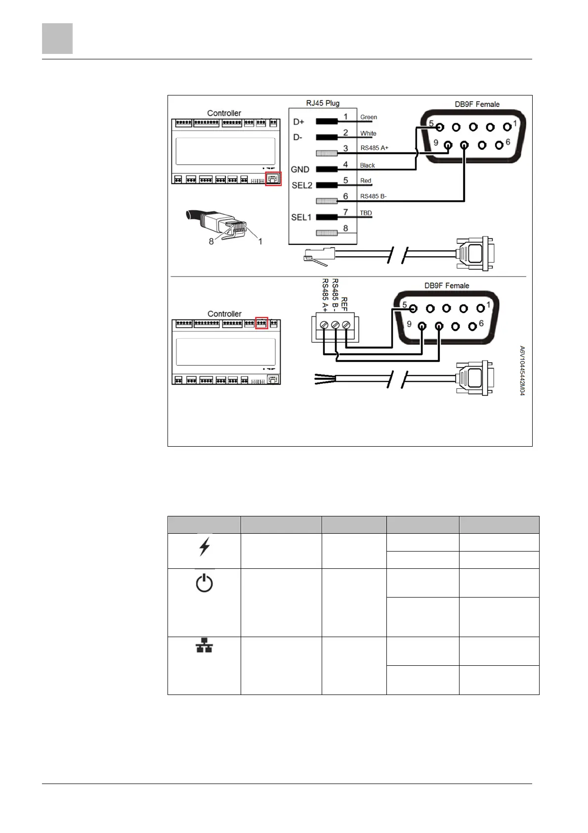
The RS485 connection is shown as an example.
Note: Accessory POL0C1.45/STD (touch panel-controller communication cable)
has an RJ45 connector. To connect the touch panel to Climatix controller RS485
port, cut-off plug and connect three wires. If a customized cable is used, ensure
that the cable length is less than 3 m.
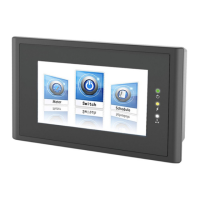
8.3 LED indicators
The three LED indicators are located on the front of the Climatix touch panel.
Marking Indicator name Color Mode Description
Power supply Green On Powered on
Off No power
Operation Yellow On
No detected
fault
Off
CPU fault
detected in the
device
Communication Yellow Flashing
Communication
in progress
Off
No
communication
Communication cable
(POL0C1.45/STD)