Gasket for panel mounting
KNX PL-Link bus connector
Base plate with
● screw holes for all common conduit
boxes
● guide channels for wiring from center,
up, or bottom
Jack connector for tool connection
2.5 Diagrams
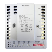
2.5.1 Connection terminals
KNX PL-Link plug
To find the location of the KNX PL-Link plug, refer to Mechanical design
NOTICE! Users can choose either pair of the pins to connect.
Wires are NOT interchangeable!
The device is protected against faulty wiring, but communications does not work
on interchanged wires. The KNX / KNX PL-Link bus MUST NOT be connected to
the tool plug, only the tool.

 Loading...