Device description
3.6 6ES7972-0Bx70-0XA0
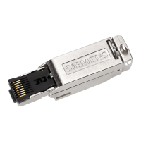
PROFIBUS bus connector
Equipment Manual, 02/2021, A5E50543113-AA
27
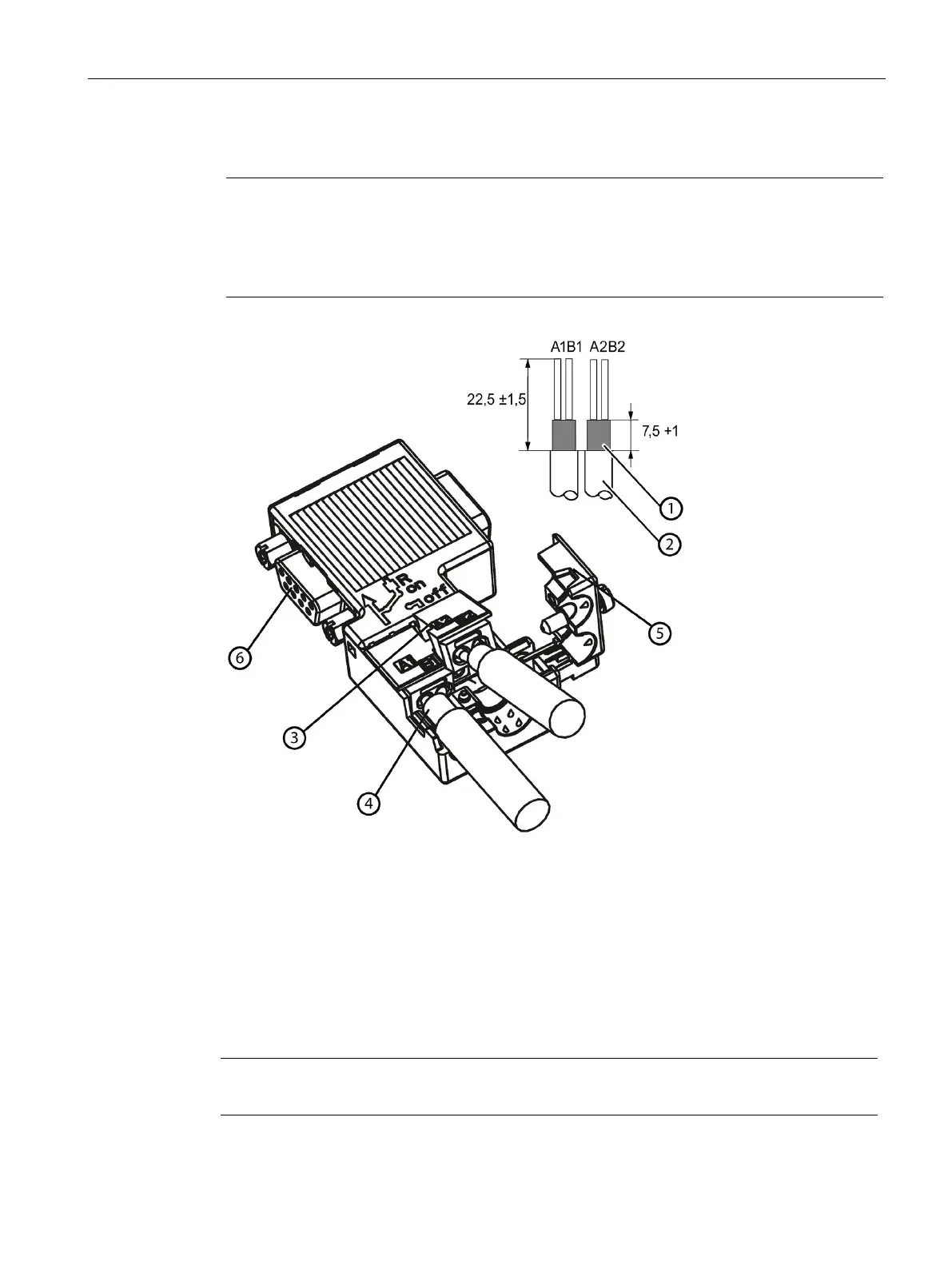
Bus cable assembly
Note
Connection of the bus lines
The bus lines are connected using
an insulation displacement system (Fast Connect). The
insulation displacement terminals are designed to withstand 10 terminating cycles. If you
want to reconnect a line that has already been connected, you must first cut it off.
Bus cable (e.g. 6XV1 830-0EH10) - strip insulation, e.g. with stripping tool 6GK1905-6AA00
3 Contact cover for insulation displacement terminal
- Insert the green and red wires into the open contact cover.
- Close contact cover (wires are pressed into insulation displacement terminal)
Cable shield must be bare on the metal guide
Close strain relief and screw down
PG socket (only for 6ES7972-0BB70-0XA0)
Note
Do not pull the mounted bus cable to open the contact cover!