Device description
3.6 6ES7972-0Bx70-0XA0
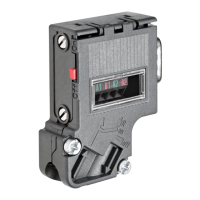
PROFIBUS bus connector
28 Equipment Manual, 02/2021, A5E50543113-AA
Bus connection for the first and last station on the PROFIBUS
Cable must always be connected on the left (see marking A1, B1), switch position must be
"ON" for the first and last station on the PROFIBUS. (terminating resistor switched on).
Note
If the switch is set to ON, the PROFIBUS to t
he other stations is disconnected at this point
(e.g. for service purposes).
Bus connection for all other stations on the PROFIBUS
Cable feed must always be connected on the left (see marking A1, B1). Cable continuation
must always be connected on the right (see label A2, B2). Switch position must be "OFF" for
all other stations on the PROFIBUS. (terminating resistor switched off).
Danger to life from live parts
• Explosion hazard - Do not disconnect circuit while power is present unless area is known
to be non-hazardous.
• Explosion hazard - Replacement of components may adversely affect approval for
Equipment Group I, Category 2 or Zone 2.
• This device is approved for operation in Equipment Group I, Category 2, Groups A, B, C,
D; Equipment Group I, Zone 2; Equipment Group IIC or non-hazardous locations.