Device description
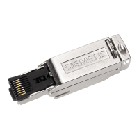
3.1 6ES7972-0Bx12-0XA0
PROFIBUS bus connector
8 Equipment Manual, 02/2021, A5E50543113-AA
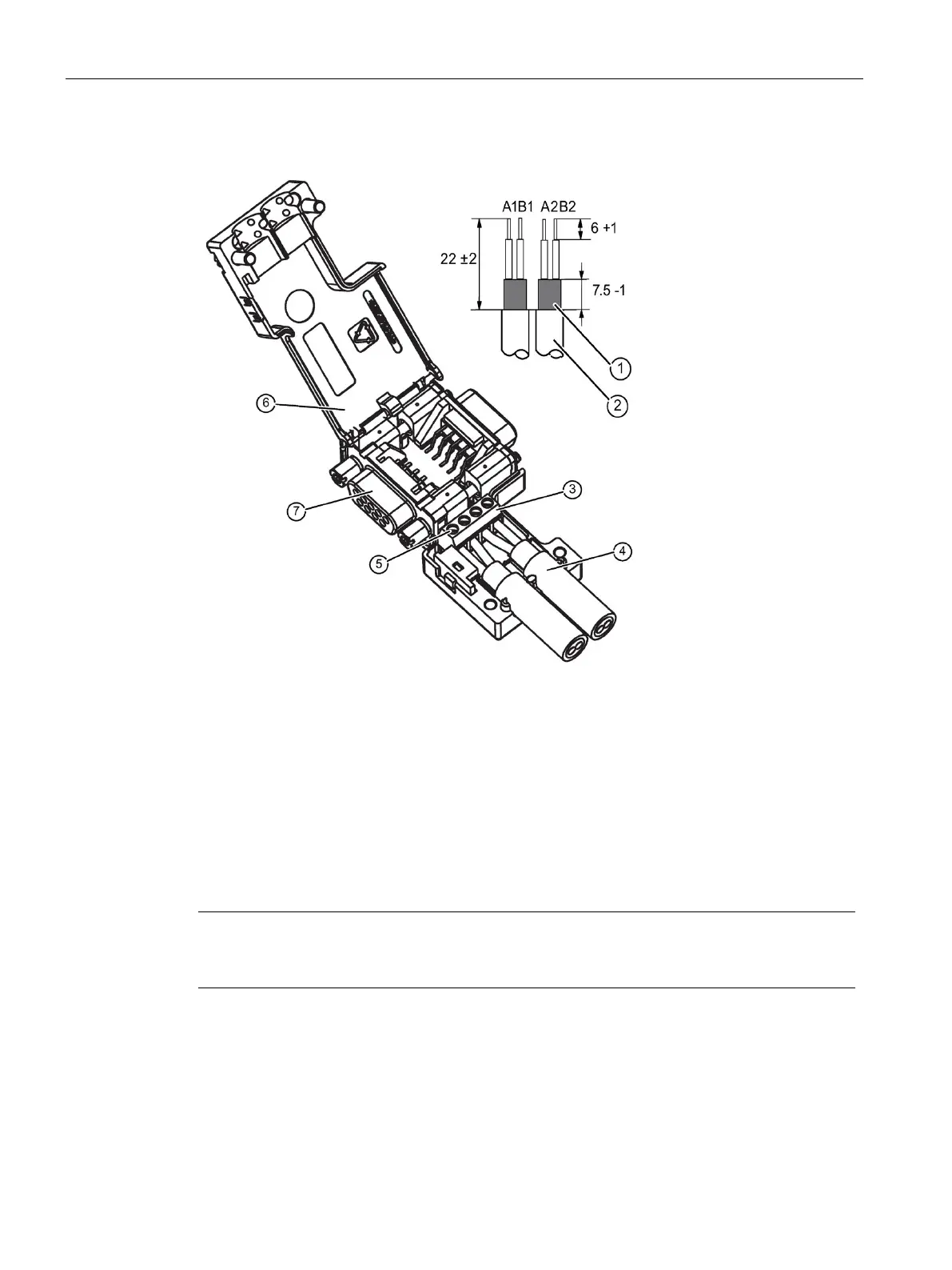
Bus cable assembly
Bus cable (e.g. 6XV1 830-0EH10) - strip insulation, e.g. with stripping tool 6GK1905-6AA00
3 Screw terminal block on connector board for bus cable connection.
- Insert green and red wire into screw terminal block (A1, B1 or A2, B2)
(Recommendation: A = green, B = red)
Press cable between the two terminal blocks. Cable shield must be stripped on contact element.
Screw the green and red wires tightly into the screw terminal.
Close the enclosure cover and screw it tight.
PG socket (only for 6ES7972-0BB12-0XA0)
Note
If the switch is set to ON, the PROFIBUS to the other stations is disconnected at this point
(e.g. for service purposes).
Bus connection for the first and last station on the PROFIBUS
Cable must always be connected on the left (see marking A1, B1), switch position must be
"ON" for the first and last station on the PROFIBUS. (terminating resistor switched on).