Device description
3.1 6ES7972-0Bx12-0XA0
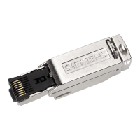
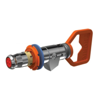
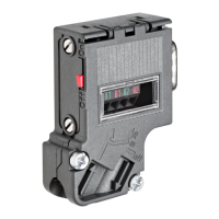
PROFIBUS bus connector
Equipment Manual, 02/2021, A5E50543113-AA
9
Bus connection for all other stations on the PROFIBUS
Cable feed must always be connected on the left (see marking A1, B1). Cable continuation
must always be connected on the right (see label A2, B2). Switch position must be "OFF" for
all other stations on the PROFIBUS. (terminating resistor switched off).