102/221
Siemens Switzerland Ltd User manual RVS61.843 CE1U2355en_02
HVAC Products 6 The settings in detail 23. November 2007
6.12 Heat pump
The heat pump draws energy from the environment (brine, water or air) and delivers it
to the heating system at a higher temperature level. If the heat pump is equipped with a
process reversing valve, it can also be used for active cooling. Also, brine-to-water and
water-to-water heat pumps can be employed for passive cooling.
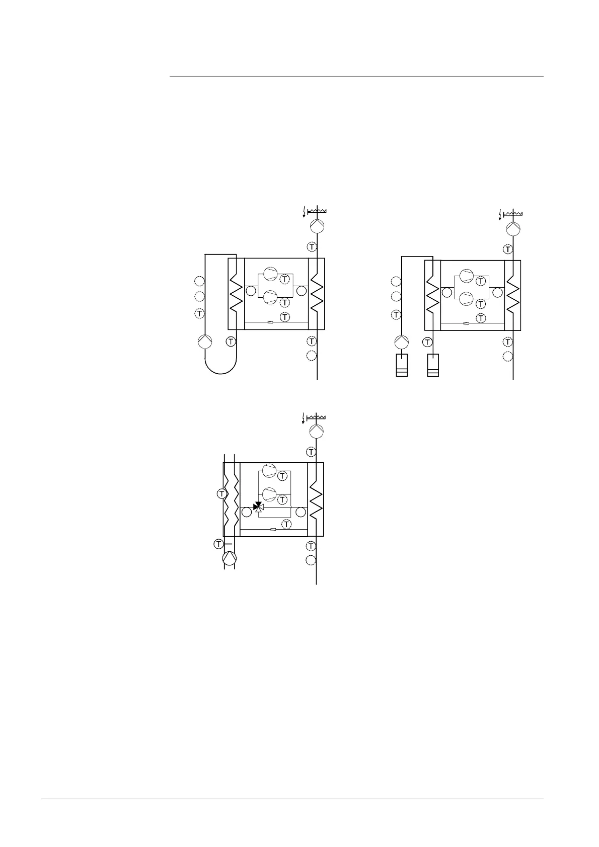
Function diagrams
The following function diagrams show the components and designations used in the
description:
Brine-to-water heat pump Water-to-water heat pump
B21
K1/E11
B71
B92
B91
E26
P
E15
F
Q8/E14
Q9
E9
P
P
B81
E10
B83
K2/E12
B82
E24
F
K25/26
B21
K1/E11
B71
Q9
E9
P
P
B81
E10
B92
Q8/E14
B91
E26
P
E15
F
K2/E12
B82
E24
F
B83
K25/26
Air-to-water heat pump
K1/E11
B71
E9
P
P
B81
E10
B83
Y22
B91
B84
K19/E14
K2/E12
B82
B21
Q9
E24
F
K25/26
Mains voltage
K25 Electric immersion heater 1
E5 Low-tariff K26 Electric immersion heater 2
E6 Heat pump lock Q8 Source pump
E9 Low-pressure switch Q9 Condenser pump
E10 High-pressure switch Y22 Process reversing valve
air-to-water heat pump
E11 Compressor 1 overload
E12 Compressor 2 overload
Low-voltage
E14 Overload source / fan B21 Flow temperature heat pump
E15 Flow switch source B71 Return temperature heat pump
E17 Manual defrost B81 Hot-gas temperature compressor 1
E24 Flow switch consumers B82 Hot-gas temperature compressor 2
E26 Pressure switch source B83 Refrigerant temperature liquid
K1 Compressor 1 B84 Evaporator temperature
air-to-water heat pump
K2 Compressor 2 B91 Source inlet temperature
K19 Fan air-to-water heat pump B92 Source outlet temperature
 Loading...