184/221
Siemens Switzerland Ltd
User manual RVS61.843 CE1U2355en_02
HVAC Products 6 The settings in detail 23. November 2007
This rule applies to relays defined as NO contacts. When defined as NC contacts, the
action is reversed.
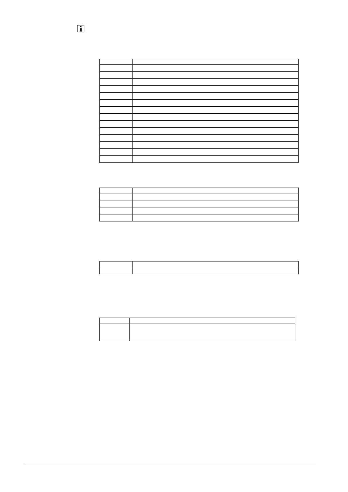
Setpoints and actual values
Line no. Operating line
8410 Return temp HP
8411 Setpoint HP
8412 Flow temp HP
8413 Compressor modulation
8415 Hot-gas temp 1
8416 Hot-gas temp max
8417 Hot-gas temp 2
8420 Refrig temp liquid
8425 Temp diff condenser
8426 Temp diff evaporator
8427 Source inlet temp
8428 Source inlet temp min
8429 Source outlet temp
8430 Source outlet temp min
These operating lines are used to query the different setpoints and actual values of the
heat pump.
Line no. Operating line
8440 Remain stage 1 off time min
8441 Remain stage 2 off time min
8442 Remain stage 1 on time min
8443 Remain stage 2 on time min
If the “Min off time“ or “Min on time“ of stage 1 or 2 is active, these operating lines show
the remaining off time / on time.
Only on completion of the off time is - - - displayed, and the heat pump can be released
again.
Line no. Operating line
8444 Remain limit source temp min
If the source temperature (B91) is too low, pumps and compressor are locked for the
period of time “Time limit source temp min“ (2822). This operating line shows the
remaining period of time for pumps and compressor to be released again.
Line no. Operating line
8446 Compressor sequence
1 – 2
2 – 1
Shows the current compressor sequence, that is, the order in which the compressors
are put into operation:
1 – 2
First, compressor 1 is put into operation, then compressor 2.
2 – 1
First, compressor 2 is put into operation, then compressor 1.
Remaining times
Remain limit source temp
min
Compressor
Compressor sequence
 Loading...